Rikon 70-305 handleiding
Handleiding
Je bekijkt pagina 9 van 24
9
FIG. 1
ASSEMBLY
FIG. 2
FIG. 3
If the lathe is to be free-standing, the four adjustable feet
should be installed onto the bottom pads of the leg stand.
See below.
If the lathe is to be permanently bolted to the oor, do NOT
install the four adjustable feet. The holes in the leg pads
will be used for installing the bolts through the leg pads and
into the oor.
1. If the lathe is to be free-standing, before attaching the
legs to the lathe bed, install the four adjustable feet onto
the bottom pads of the legs.
2. The adjustable Feet (#A28) have three hex nuts (#A27)
pre-assembled on the threaded shafts. Remove the top nut
and leave the bottom two nuts on the shaft. These two nuts
will be used to adjust the level of the lathe later on. FIG. 1.
3. Insert the threaded shaft through the hole in the bottom
of the leg pad, and re-install the top nut onto the shaft to
secure the foot onto the leg. Do not fully tighten the nut at
this time.
4. Install the other three adustable feet on the other three
leg pads.
5. Once the lathe is assembled and in its nal locaton, ad-
just the feet nut(s) to level the lathe, then tighten the nuts.
INSTALL THE FEET ONTO THE LEGS
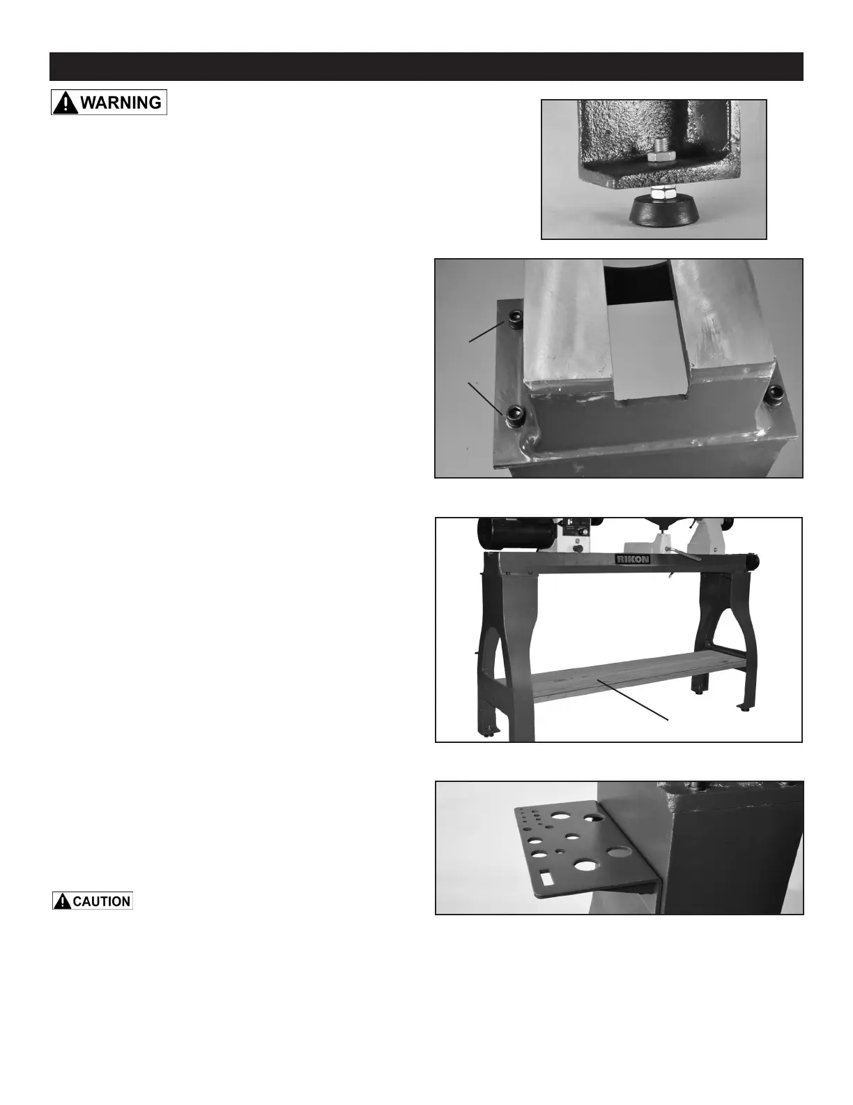
INSTALL THE LATHE BED ONTO THE LEGS
1. Position the two stand legs approximately 59-1/4” apart
measuring from the outside edges. Be sure that the shelf
brackets on the legs are facing inward, towards each other.
2. Secure Headstock (#B11), Tailstock (#A20), and Tool
Rest (#A7) assemblies to the Lathe Bed (#A2) by tightening
their locking Lever Handles. See page 11 of this manual on
how to make these adjustments.
3. With assistance, lift up the lathe bed assembly and
carefully position it onto the stand legs to align the bolt
holes.
Lift the lathe body by the bed only, not by the
motor, headstock, tailstock, or tool rest assemblies.
4. Secure the lathe bed to the stand legs with the eight
Hex Head Bolts (#A23) and Flat Washers (#A24) . FIG. 2.
5. NOTE: A shelf can be added between the legs for stor-
age of tools, turning supplies or for extra weight. Use 2x4s
and thick plywood to construct this shelf to your specic
design or storage needs. (Plans are not available). FIG. 3.
INSTALL THE TOOL HOLDER
Install the Tool Holder (#A31) onto the outside surface of
the left Stand Leg (#A1) with the two hex head mounting
Screws (#A30) provided. This holder includes multiple
holes for convenient storage of wrenches, centers, tool
rests and other lathe accessories. FIG. 3A.
ADD A SHELF FOR STORAGE
LATHE
BED
LEG
BOLTS &
WASHERS
THE MACHINE MUST NOT BE
PLUGGED IN AND THE POWER SWITCH MUST BE IN THE
OFF POSITION UNTIL ASSEMBLY IS COMPLETE.
FIG. 3A
Bekijk gratis de handleiding van Rikon 70-305, stel vragen en lees de antwoorden op veelvoorkomende problemen, of gebruik onze assistent om sneller informatie in de handleiding te vinden of uitleg te krijgen over specifieke functies.
Productinformatie
| Merk | Rikon |
| Model | 70-305 |
| Categorie | Niet gecategoriseerd |
| Taal | Nederlands |
| Grootte | 6904 MB |


