Rikon 70-1824VSR2 handleiding
Handleiding
Je bekijkt pagina 10 van 40
ASSEMBLY
THE MACHINE MUST NOT BE
PLUGGED IN AND THE POWER SWITCH MUST BE IN
THE OFF POSITION UNTIL ASSEMBLY IS COMPLETE.
The 70-1824VSR Lathe has a oor-to-spindle height of
approximately 43-5/16” (1100mm).
If this working height is ne, then the lathe can be used
as is.
1. Install the provided 4 Rubber Foot Pads (V) onto the
bottoms of the lathe Legs (O) to reduce any possible
vibration or lathe ’walking’ during use. Figure 1.
2. Assemble the legs to the lathe body. See page 11.
For best stability, it is recommended that the lathe be bolted
to the oor. The bottom of the lathe’s feet have 11/16”
(17mm) diameter holes to allow fasteners to bolt them to
the oor. Fasteners (lag bolts, screws, washers, etc.) are
not provided.
NOTE: If the lathe is to be permanently bolted to the oor,
DO NOT install adjustable feet (see below) which also use
the holes in the feet for installation. Riser blocks or shims
will have to be made by the user to put under the legs to
level the lathe and/or raise the lathe height before bolting
the lathe to the oor.
If the lathe’s working height is too low, then a set of four
Adjustable Feet (70-972) are available to be installed onto
the bottom of the legs. Figure 2. These feet can be installed
onto the legs if the rubber pads are installed or not.
See page 37 for information on these optional accessories.
1. Before attaching the legs to the lathe bed, install the
optional four adjustable feet onto the bottom of the legs.
These will raise the 43-5/16” spindle height approximately
1-3/4” to 2-1/2” more.
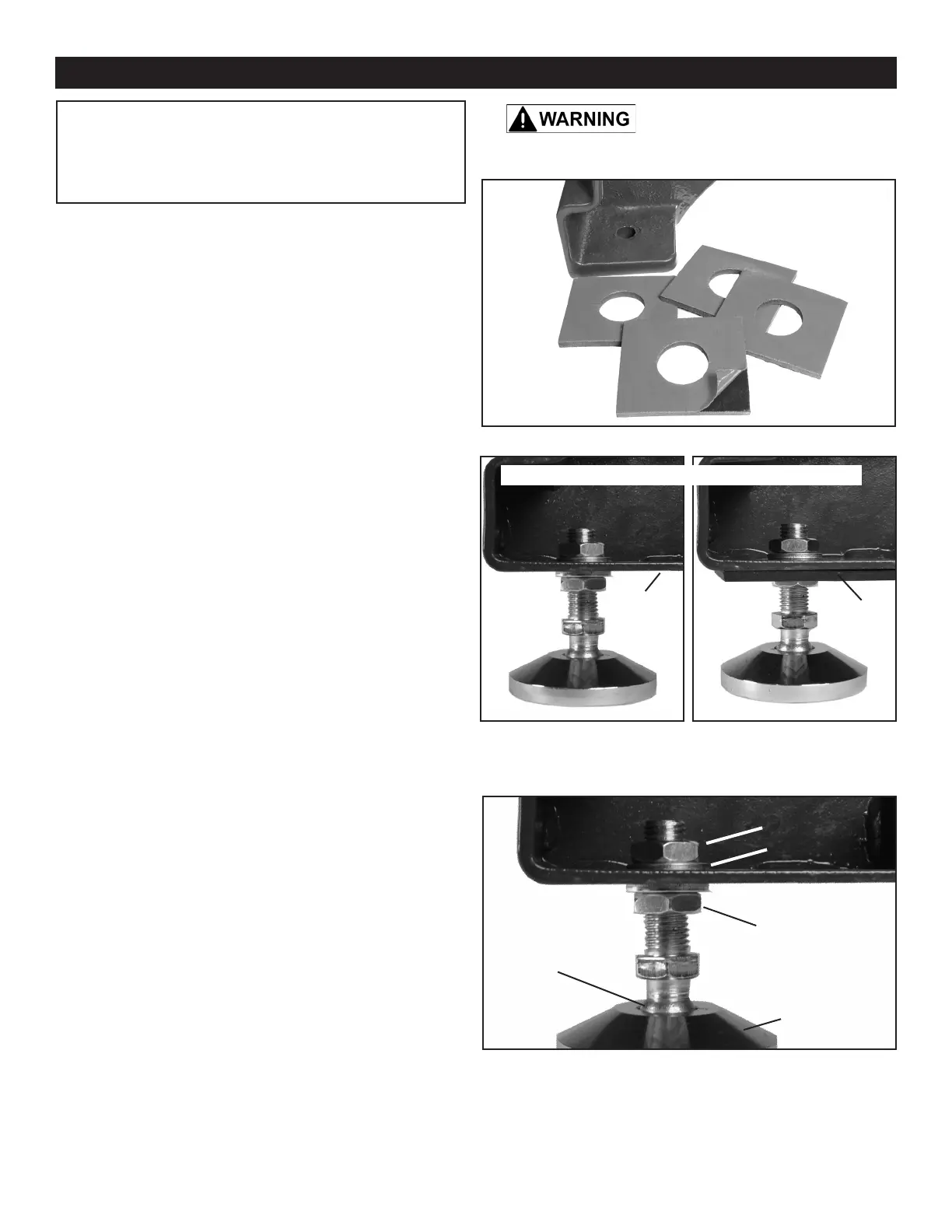
2. The Adjustable Feet have two hex nuts and washers
assembled on their threaded shafts. Remove the top
nut and washer (Fig. 3, A) and leave the bottom nut and
washer on the shaft. The bottom nut will be used to adjust
the level of the lathe later on. Figure 3.
3. Insert the threaded shaft through the hole in the bottom
of the leg, and re-install the top washer and nut onto the
shaft to secure the foot onto the leg. Do not fully tighten the
nut at this time.
4. Install the other three adjustable feet on the other three
legs following steps 2 and 3 above.
5. Assemble the legs to the lathe body. See page 11.
INSTALL THE PADS OR FEET ONTO THE LEGS
FIG. 1
NOTE: The parts listed in the instructions refer
to either the Contents of Package on page 9 (A,
B, C...), and/or the Parts Diagram & Parts List on
pages 29 & 36 (Sheet A part #4 is listed as #4A, etc.).
FIG. 2
10
NOTE: Once the lathe is assembled and in its nal location,
adjust the bottom nut(s) (Fig. 3, C) that are right under the
bottom of the foot to set your desired spindle height and to
level the lathe. Once set, then tighten the top nuts to secure
the adjustable feet in position.
FIG. 3
B
C
NOTE: For clarity, gures 2A & 3 are shown without the anti-vibration
rubber foot pads attached on the bottom of the lathe legs.
A
B
WITH
RUBBER
PAD
WITHOUT
RUBBER
PAD
FOOT
A
SWIVEL
JOINT
Adjustable Feet (70-972) are Optional Accessories
Bekijk gratis de handleiding van Rikon 70-1824VSR2, stel vragen en lees de antwoorden op veelvoorkomende problemen, of gebruik onze assistent om sneller informatie in de handleiding te vinden of uitleg te krijgen over specifieke functies.
Productinformatie
| Merk | Rikon |
| Model | 70-1824VSR2 |
| Categorie | Niet gecategoriseerd |
| Taal | Nederlands |
| Grootte | 13415 MB |


