RIDGID 918-5 handleiding
Handleiding
Je bekijkt pagina 14 van 111
918 Roll Groover
999-998-946.10_REV D
12
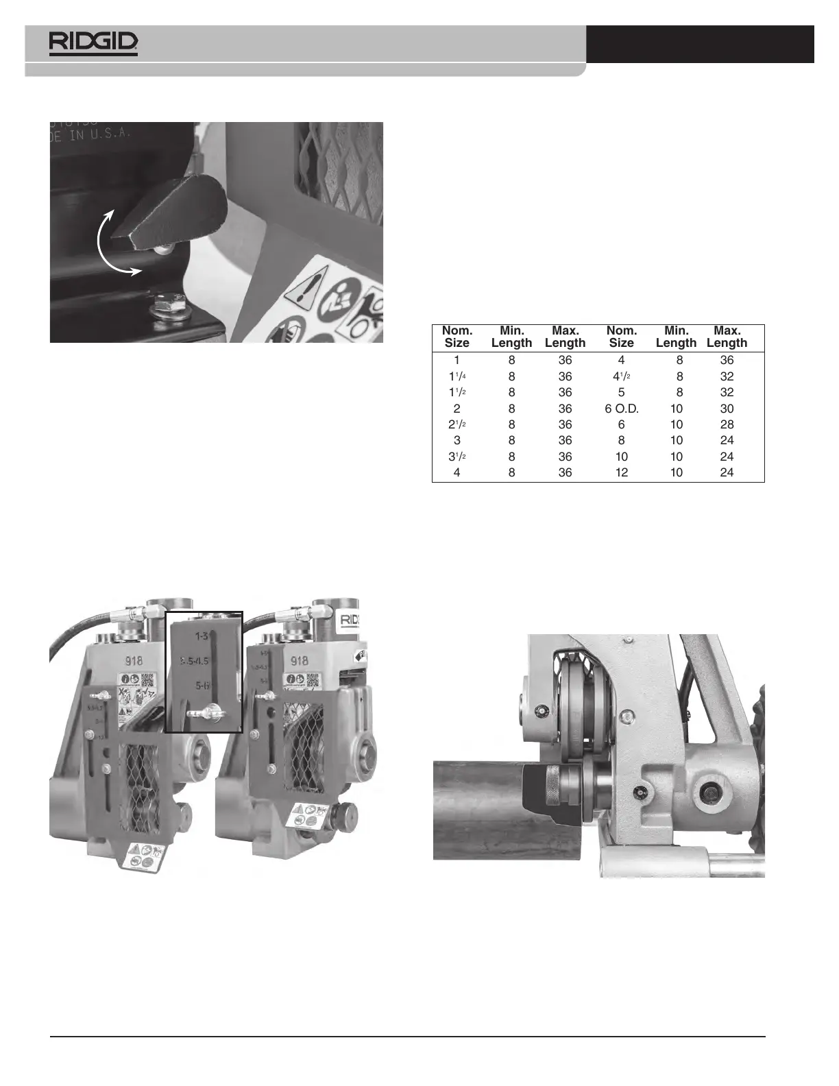
Figure 11 – Pump Release Lever Position
Setting Adjustable Guard
1. Confirm the size of the pipe that is going to be
grooved.
2. Locate the engraved pipe sizes on the guard face.
Find the range of sizes that the pipe falls within.
3. Loosen the wing-screw. Adjust the position of the
guard so that the correct range of sizes aligns with
the position of the wing-screw. Properly adjust guard
to reduce the risk of entanglement and serious injury
(Figure 12).
4. Securely tighten the wing screw.
Figure 12 – Setting Adjustable Guard
Loading Pipe in Roll Groover
1. Confirm that the machine switch is in the OFF posi-
tion.
2. Fully retract the groove roll.
3. Appropriate pipe stands must be available to support
the pipe. Adjust the height of the pipe stands so that
the pipe will be level and the top inner diameter of the
pipe will sit on top of the drive roll (see Figure 13).
Place the pipe stands directly in front of the roll
groover. Pipe stand placement depends on the pipe
length.
For shorter pipe (see Chart A) the pipe is supported
by the drive shaft and at least one stand. In this case,
the stand should be placed slightly more than half
the length of the pipe from the roll groover.
Chart A – Minimum/maximum pipe length to be grooved
with one stand (in inches)
For longer pipes at least two stands should be used,
with the two stands placed approximately 1/4 of the
pipe length from the ends of pipe. Failure to properly
support the pipe may allow the pipe or the pipe and
machine to tip and fall. Always use a pipe stand – it
helps to align the pipe and maintain proper tracking.
Figure 13 – Placing Pipe over Drive shaft, Flush to drive
shaft flange (Stabilizer removed for clarity)
4. Place the pipe on the stand(s) with the end of the
pipe flush to the drive shaft flange and the inside of
the pipe contacting the top of the drive shaft (Figure
13). Make sure the pipe is stable and secure.
Advance
Retract
Nom. Min. Max. Nom. Min. Max.
Size Length Length Size Length Length
1 8 36 4 8 36
1
1
/
4
8 36 4
1
/
2
8 32
1
1
/
2
8 36 5 8 32
2 8 36 6 O.D. 10 30
2
1
/
2
8 36 6 10 28
3 8 36 8 10 24
3
1
/
2
8 36 10 10 24
4 8 36 12 10 24
Bekijk gratis de handleiding van RIDGID 918-5, stel vragen en lees de antwoorden op veelvoorkomende problemen, of gebruik onze assistent om sneller informatie in de handleiding te vinden of uitleg te krijgen over specifieke functies.
Productinformatie
| Merk | RIDGID |
| Model | 918-5 |
| Categorie | Niet gecategoriseerd |
| Taal | Nederlands |
| Grootte | 42226 MB |


