Pro1 T725 handleiding
Handleiding
Je bekijkt pagina 2 van 4
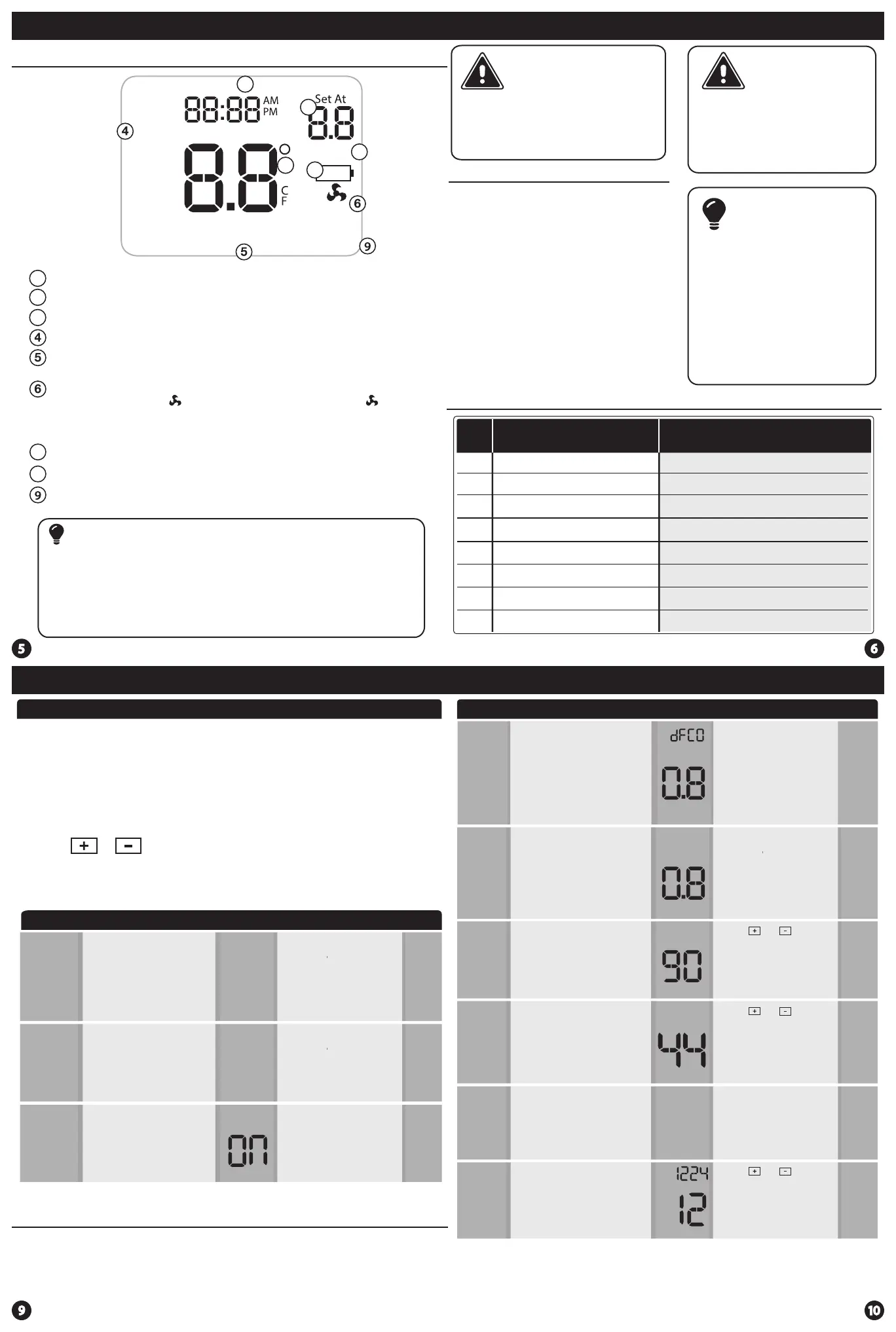
Thermostat Quick Reference
Wiring
Tech Settings Tech Settings
This thermostat has a technician setup menu for easy installer
conguration. To setup the thermostat for your particular application:
Swing Setting Tip
Temperature swing, sometimes called dierential or cycle rate, can be customized
for this individual application. For most applications choose a swing setting that is
as long as possible without making the occupants uncomfortable.
Technician Setup Menu
LCD Will Show
The compressor short cycle delay
protects the compressor from
short cycling. This feature will not
allow the compressor to be turned
on for 5 minutes after it was last
turned o.
Selecting “ON” will not allow
the compressor to be turned on
for 5 minutes after the last time
the compressor was switched
o. Select “OFF” to remove this
delay.
0
This feature allows the installer
to change the calibration of the
room temperature display. For
example, if the thermostat reads
70˚ degrees and you would like it
to read 72˚ then select +2.
Room
Temperature
Calibration
You can adjust the room
temperature display to read
4˚above or below the factory
calibrated reading.
Tech Settings
Adjustment Options
Compressor
Short Cycle
Delay
Default
0N
Cd
0.8
The swing setting often called
“cycle rate”, “dierential” or “
anticipation” is adjustable. A
smaller swing setting will cause
more frequent cycles and a larger
swing setting will cause fewer
cycles.
Cooling
Swing
The cooling swing setting is
adjustable from 0.2˚ to 2˚. For
example: A swing setting of
0.5˚ will turn the cooling on at
approximately 0.5˚ above the
setpoint and turn the cooling
o at approximately 0.5˚ below
the setpoint.
0FF
This feature will ash “FILT” in the
display after the elapsed run time
to remind the user to change the
lter. A setting of “OFF” will disable
this feature.
Filter Change
Reminder
You can adjust the lter change
reminder from OFF to 2000
hours of runtime in 50 hour
increments.Tap the second
button from the top left side of
the thermostat to display the
current lter elapsed runtime.
F1
Next Step
Prev Step
100
SE
0
Next Step
Prev Step
CAL
Next Step
Prev Step
Next Step
Prev Step
Use the or keys to change settings and the NEXT STEP or
PREV STEP key to move from one step to another. Note: Only press
the DONE key when you want to exit the Technician Setup options.
1. Press the MENU button
2. Press and hold TECH SET button for 3 seconds. This 3 second
delay is designed so that homeowners do not accidentally access
the installer settings.
3. Congure the installer options as desired using the table below.
Tech Settings
Adjustment Options Default
The swing setting often called “cycle
rate”, “dierential” or “anticipation”
is adjustable. A smaller swing
setting will cause more frequent
cycles and a larger swing setting
will cause fewer cycles.
The heating swing setting is
adjustable from 0.2˚ to 2˚. For
example: A swing setting of
0.5˚ will turn the heating on at
approximately 0.5˚ below the
setpoint and turn the heating
o at approximately 0.5˚ above
the setpoint.
Heating
Swing
0.8
Next Step
Prev Step
This feature allows you to set a
minimum cool setpoint value. The
setpoint temperature cannot be
lowered below this value.
Cooling
Setpoint
Limit
44
Use the and key to
select the minimum cool
setpoint.
This feature allows you to set a
maximum heat setpoint value. The
setpoint temperature cannot be
raised above this value.
Heating
Setpoint
Limit
90
Use the and key to
select the maximum heat
setpoint.
Next Step
Prev Step
Next Step
Prev Step
CO L
Select F for Fahenheit temperature
read out or select C for Celsius
read out.
F for Fahrenheit
C for Celsius
F or C
F
F
FC
You can select either a 12 or 24 hour
clock setting.
12 or 24
Hour Clock
12
Use the and to select 12
or 24 hour clock.
Next Step
Prev Step
Next Step
Prev Step
HE L
dFHE
LCD Will Show
The low battery indicator is displayed when the AA battery power is low. If the user
fails to replace the battery within 21 days, the screen will only show the low battery
indicator but maintain all functionality. If the user fails to replace the batteries after
an additional 21 days (days 22-42 since rst “low battery” display) the setpoints will
change to 55˚F (Heating) and 85˚F (Cooling). If the user adjusts the setpoint away from
either of these, it will hold for 4 hours then return to either 55˚F or 85˚F. After day 63
the batteries must be replaced immediately to avoid freezing or overheating because
the thermostat will shut the unit o until the batteries are changed.
Important
Indicates the current room temperature
Time and day of the week
Setpoint: Displays the user selectable setpoint temperature.
Hold is displayed when the thermostat program is permanently overridden.
System Operation Indicators:
The COOL ON, HEAT ON or icon will display when the COOL, HEAT, or (fan) is on.
Note: The Compressor delay feature is active if these are ashing.
Low Battery Indicator: Replace batteries when this indicator is shown.
Button Options
Program Time Periods: This thermostat has 4 programmable time periods
per day.
Getting to know your thermostat
Hold
LOW
COOL ON
EmHEAT ON
Sun Mon Tue Wed Thu Fri Sat
Temperature
Tech Set
Next Step
Set Time
Run Sched
Set Sched
Hold
Prev Step
Menu
Done
LEAVE SLEEP
RETURN WAKE
Stage 1 & 2
Stages: Indicates the stages of heat that are active.
Caution:
Electrical Hazard
All components of the
control system and the
thermostat installation must
conform to Class II circuits
per the NEC Code.
Warning:
Do not overtighten terminal
block screws, as this can
damage the terminal block.
A damaged terminal block
can keep the thermostat
from tting on the subbase
correctly or cause system
operation issues.
Installation Tip
Max Torque = 6in-lbs.
Wiring
If you are replacing a thermostat,
make note of the terminal
connections on the thermostat
that is being replaced. In some
cases the wiring connections will
not be color coded. For example,
the green wire may not be
connected to the G terminal.
Loosen the terminal block
screws. Insert wires then
retighten terminal block screws.
Place nonammable insulation
into wall opening to prevent
drafts.
1.
2.
3.
Terminal Designations
R
Failure to disconnect the power
before beginning to install this
product can cause electrical
shock or equipment damage.
C
B
O
G
W/E
W2
Y
Heat Pump System
1 HEAT 1 COOL / 2 HEAT 1 COOL
Conventional System
1 HEAT 1 COOL / 2 HEAT 1 COOL
Transformer Power
Transformer Common
Changeover Valve
Energized in HEAT
Fan Relay
First Stage of Emergency HEAT
Changeover Valve
Energized in COOL
Second Stage of HEAT/
EMERGENCY HEAT
First Stage of HEAT and COOL
Transformer Power
Transformer Common
Fan Relay
First Stage of HEAT
Second Stage of HEAT
First Stage of COOL
Energized in HEAT
Energized in COOL
1
2
3
7
8
1
3
2
7
8
Bekijk gratis de handleiding van Pro1 T725, stel vragen en lees de antwoorden op veelvoorkomende problemen, of gebruik onze assistent om sneller informatie in de handleiding te vinden of uitleg te krijgen over specifieke functies.
Productinformatie
| Merk | Pro1 |
| Model | T725 |
| Categorie | Niet gecategoriseerd |
| Taal | Nederlands |
| Grootte | 1055 MB |
