Power Soak Power Prep Advanced PPA2B-66 handleiding
Handleiding
Je bekijkt pagina 7 van 12
7 OM-POWER PREP ADVANCED
EQUIPMENT DESCRIPTION
# of Bays
Model No. Length Voltage Flow
FLOW CONFIGURATION
End Splash
Soiled Drain Board
Wash Tank
Clean Drain Board
End Splash
2
PPA2B-66L-115-1
66”
115/60/1
Left to Right
Hemmed
18"
18" x 19"
30"
Hemmed
PPA2B-66L-208-1 208/60/1
PPA2B-66L-230-1 230/60/1
PPA2B-66R-115-1 115/60/1
Right to Left
PPA2B-66R-208-1 208/60/1
PPA2B-66R-230-1 230/60/1
2
PPT2B-104L-115-1
104”
115/60/1
Left to Right
1-1/2"
18"
18" x 19"
48"
1-1/2"
PPT2B-104L-208-1 208/60/1
PPT2B-104L-230-1 230/60/1
PPT2B-104R-115-1 115/60/1
Right to Left
PPT2B-104R-208-1 208/60/1
PPT2B-104R-230-1 230/60/1
INSTALLATION
FAILURE TO INSTALL THE INTAKE SCREEN WILL ALLOW FOOD TO ENTER
THE PUMP INTAKE AND CLOG THE FLUID FLOW TO THE PUMP. THIS WILL
PREVENT THE MACHINE FROM OPERATING PROPERLY AND REQUIRE A
SERVICE CALL TO REMOVE THE CLOG.
STARTING THE WASH PUMP WITHOUT THE JET CHANNEL IN PLACE WILL
CAUSE WATER TO BE SPRAYED OUT OF THE WASH SINK WITH ENOUGH
VELOCITY TO WET THE FLOOR AND THE OPERATOR.
THE INSTALLATION AND INITIAL OPERATIONAL CHECK OF THE POWER
PREP ADVANCED UNIT MUST BE PERFORMED BY LICENSED AND CERTIFIED
PLUMBERS AND ELECTRICIANS.
BE SURE TO FOLLOW ALL NATIONAL AND LOCAL ELECTRICAL CODES WHEN
INSTALLING THE ELECTRICAL SUPPLY AND/OR A NEW CIRCUIT BREAKER.
DO NOT CONNECT THE SYSTEM USING A POWER CORD AND PLUG OR AN
EXTENSION CORD OF ANY KIND.
DO NOT CONNECT THE MACHINE USING A POWER CORD AND PLUG OR
AN EXTENSION CORD OF ANY KIND. KITCHENS ARE WET ENVIRONMENTS
WHICH REQUIRE ALL ELECTRICAL CONNECTIONS TO BE “LIQUID TIGHT.”
ELECTRICAL INSTALLATION MUST CONFORM TO ALL APPLICABLE
NATIONAL AND LOCAL WIRING CODES. ALL ELECTRICAL CONNECTIONS
MUST BE READILY ACCESSIBLE FOR INSPECTION AFTER INSTALLATION
WITHOUT MOVING THE POWER PREP ADVANCED MACHINE OR ANY OF ITS
ACCESSORIES.
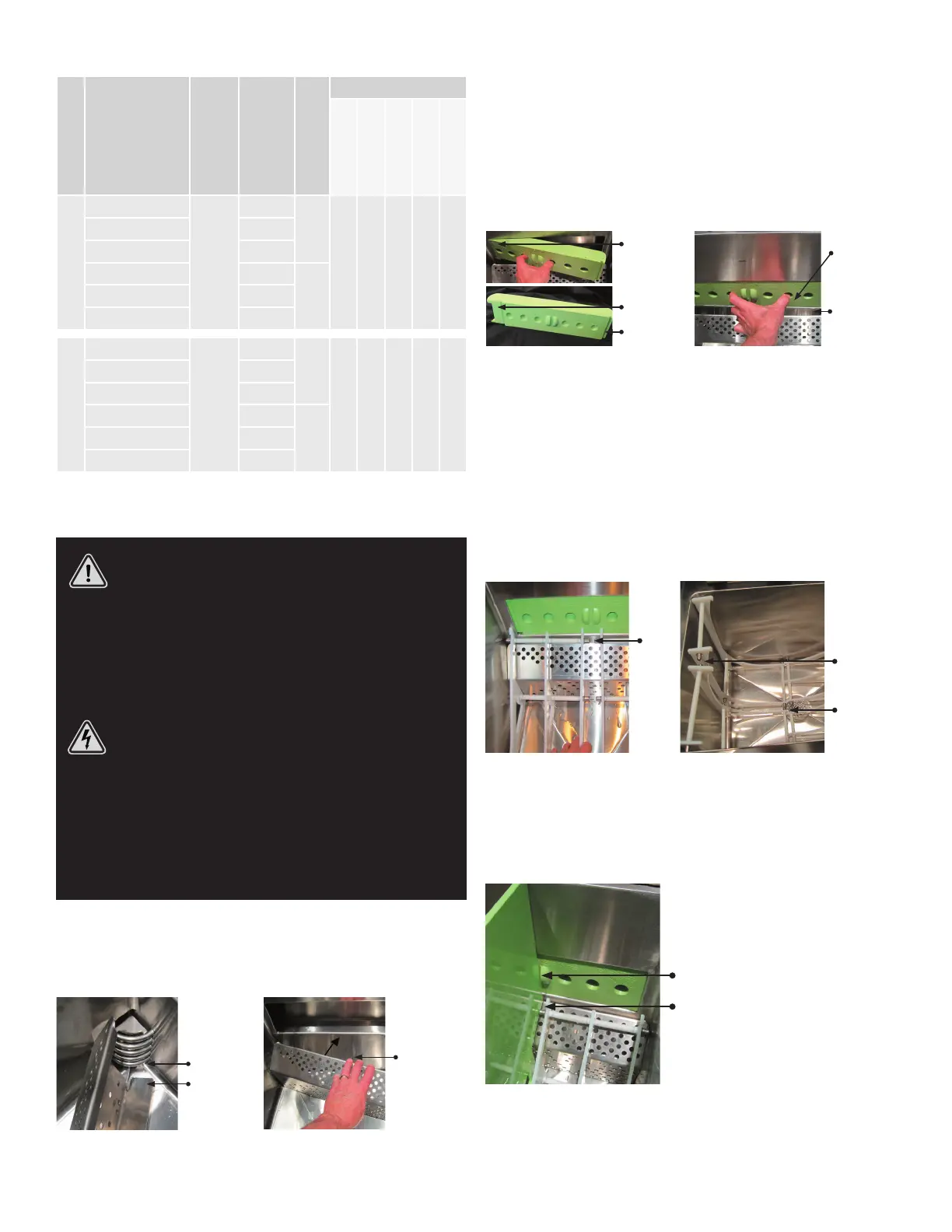
INSTALLING COMPONENTS IN THE WASH SINK
Before installing the components in the wash sink, inspect the sink, the channel in
the back wall and all of the components to be sure they are clean and free of debris.
Installing the Intake Screen:
Rotate the screen
into position
against the back
wall while resting
on the bottom of
the sink
Intake opening
Tab on the intake
screen must insert
into the intake
opening
The illustration shows a “Left Hand” machine. A “Right Hand” machine will insert into the opening on the opposite side of
the machine.
The intake screen is removable for cleaning. It must be installed before operation of
the food washer in order to prevent food from entering the pump intake. Operating the
machine without the intake screen will cause the pump to become clogged with food.
The intake screen has a tab that prevents the screen from tting into the wash sink
in the wrong orientation. The tab must be inserted into the intake opening in order to
place the screen into its operating position.
1. Rotate the screen into position against the back wall while resting on the bottom
of the sink.
Installing the Jet Channel:
Slide away from
the pump until
short extension
is behind metal
Long extension
Insert the long
extension into
the opening of
the back wall
The illustration shows a “Left Hand” machine. A “Right
Hand” machine will insert into the other end of the opening.
Short extension
Reverse the installation steps to remove the jet channel.
Instructions for removing the jet channel are imprinted on
its face.
Swing into the
opening until it
stops
The jet channel must be installed in the discharge manifold before starting the wash
pump. Insert the end with the long extension into the pump end of the discharge
manifold. Swing the jet channel into the opening until it stops, then slide the jet
channel so that the short extension is covered by the sheet metal of the back wall.
1. Insert the long extension into the opening of the back wall.
2. Swing the jet channel into the opening until it stops.
3. Slide the jet channel away from the pump until the short extension is tucked
behind the metal.
Installing the Rib Sets:
Gap
Gap
Gap
1. Begin by placing a rear rib set against one of the rear corners of the sink. Place
the other rear rib set against the other rear corner of the sink leaving a nger-size
gap between them.
2. Place the front rib sets against the front wall of the sink. Leave a nger-size gap
between the rib sets in order to insert the divider board between the rib sets.
Placing the Divider Board:
Divider board
passes through
the slot in the jet
channel and be-
tween the metal
ends on the rib
sets until it rests
on the bottom of
the sink
1. Insert the divider board into the gap between the front and rear pairs of rib sets.
The divider board will also slide through the slot in the center of the jet channel.
Make sure the divider board slides all the way down to touch the bottom of the
sink. It may be necessary to reach into the sink and separate the rib sets as the
divider board is lowered into position.
Bekijk gratis de handleiding van Power Soak Power Prep Advanced PPA2B-66, stel vragen en lees de antwoorden op veelvoorkomende problemen, of gebruik onze assistent om sneller informatie in de handleiding te vinden of uitleg te krijgen over specifieke functies.
Productinformatie
| Merk | Power Soak |
| Model | Power Prep Advanced PPA2B-66 |
| Categorie | Niet gecategoriseerd |
| Taal | Nederlands |
| Grootte | 8966 MB |


