Panduit VS-AVT-C08-L10 handleiding
Handleiding
Je bekijkt pagina 13 van 21
© Panduit Corp. 2021
INSTRUCTION MANUAL
VeriSafe AVT
B21052_15 Page: 12 of 20 2-2022
Termination Recommendations
The VeriSafe AVT is provided with a total of (8) 14 AWG (2 mm
2
) sensor leads (two sensor leads for each phase conductor and ground
connection point). Sensor leads for each phase and ground must not be mechanically connected to each other for the AVT to function properly
(see step 7 in the Installation Instructions). The second lead on each phase provides the ability for the AVT to verify that it is in contact with
the circuit conductors (each phase and ground) when the absence of voltage test takes place. It is also part of the mechanism that is used to
“test-the-tester” to validate that the AVT is functioning. There is no maximum distance limitation between the two leads on each phase,
however there should not be any circuit elements installed between them. Do not extend the sensor leads with a splice. Use approved
connection methods and follow local codes and standards when terminating the sensor leads.
AVT sensor lead terminations should be made via a tap to the circuit conductor using connectors, terminal strips, or power distribution blocks,
etc. which are rated for the application. It is generally preferred to use connection methods that do not pierce or otherwise compromise the
integrity of the conductor. Connectors that require conductors to be cut or spliced can be used but may limit the SCCR.
Connectivity Test
Each time the absence of voltage test is initiated, the VeriSafe AVT performs a series of diagnostics and checks in addition to testing for absence
of voltage. One step in this sequence involves a “connectivity test.” The purpose of the connectivity test is to ensure that each detection lead
is in contact with a conductor.
The VeriSafe AVT is designed with two Sensor Leads for each phase conductor. The two leads for each conductor have different functions.
The Detection Lead is used to detect voltage and the Termination Lead is used to verify that the Detection Lead is in contact with a conductor.
The Termination Lead does not detect voltage. There are no labels distinguishing the Detection and Termination Leads because it is critical
that they are both properly terminated. If the Detection Lead is not contacting a conductor, the connectivity test will fail and prevent the AVT
from returning a Green Absence of Voltage indication.
The connectivity test is performed by measuring the discharge time of a capacitor inside the Isolation Module that is electrically connected to
the detection lead. If the Detection Lead is electrically connected to the Termination Lead, the discharge time will be inside the desired range
and the test will pass. If the Detection Lead is not in contact with a conductor, the discharge time will be outside of the desired range and the
test will fail. If the connectivity test fails on any Detection Lead, the green absence of voltage indicator on the AVT will not illuminate.
IMPORTANT: If the detection lead is not properly terminated to a power conductor and comes in contact with a low impedance path to
ground, the discharge time could be inside the desired range and the connectivity test would pass. This would be a multi-fault scenario, but
is possible if terminations are not made properly and secured. An AVT installed on a single-phase system might only have one Detection Lead
terminated to a power conductor. If the Detection Lead were to become loose and make contact with a low impedance path to ground, the
connectivity test would pass. However, voltage would not be detected because the termination lead does not detect voltage and the
Detection Lead is no longer in contact with the power conductor. This could result in a green absence of voltage indication, even though the
power conductor is energized. This would be less likely to occur with split-phase or three-phase systems as all Detection Lead terminations
would need to fail and each detection lead would have to make contact with a low impedance path to ground at the time of the test.
However, even the loss of a single detection lead termination on a multi-phase system could result in the scenario described above, if voltage
was only present on a single phase.
Utilization of the commissioning test described in this Instruction Manual will verify proper functionality of the AVT at the time of installation.
The failure modes described in this section would be the result of Sensor Lead terminations not being maintained over time and Sensor Leads
not being secured to the power conductors at time of installation. The likelihood of this scenario can be reduced by securing the Sensor Leads
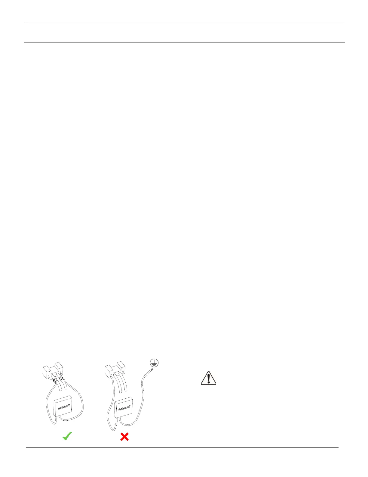
to the power conductor or another nearby rigid feature to prevent movement in the event that the termination point failed. Sensor Leads can
be secured using cable ties, clamps, mounts or tape. The sensor leads should be secured at multiple locations, including near the termination
point. Additionally, the Schematics section of this Instruction Manual provides redundant detection schematics for both single-phase and DC
installations to provide a redundant Detection Lead on the power conductor.
Warning:
Secure Sensor Leads to
prevent accidental contact
with ground.
Bekijk gratis de handleiding van Panduit VS-AVT-C08-L10, stel vragen en lees de antwoorden op veelvoorkomende problemen, of gebruik onze assistent om sneller informatie in de handleiding te vinden of uitleg te krijgen over specifieke functies.
Productinformatie
| Merk | Panduit |
| Model | VS-AVT-C08-L10 |
| Categorie | Niet gecategoriseerd |
| Taal | Nederlands |
| Grootte | 7007 MB |


