Olimpia Splendid Bi2 Wall TR handleiding
Handleiding
Je bekijkt pagina 55 van 240
Bi2 Wall TR
ENGLISH
EN - 13
2.11.b - Presence contact input
To terminals “A” and “B”,oftheinternalterminalbox,(g.15)itispossibletoconnectafreecontact,
notlive,ofapossiblepresencesensor(notsupplied)which,whenclosed,causesthedeactivationofthe
appliance(factorysettingstand-by).
Itispossible,infactoryoranauthorizedassistancecentreuponpriorrequestofthecustomer,tochange
thisfunctionsothattheselectedambienttemperatureisautomaticallyincreased(incoolingmode)or
decreased(inheatingmode)byaspecicvalue“EconomyFunction”whenthecontactisclosed.
To use this function, check that the terminals “A” and “B” are connected to the connector “X8”.
It is not possible to connect the parallel input the one of other circuit boards;
use separate contacts.
Toconnectthepresencesensor,itisnecessarytouseadouble-insulatedcablewithaminimumsection
of2x0,5mm
2
andmaximumlengthof20m.Keepthisconnectionseparatedfromthepowersupplyline
oftheappliance.
2.11.c - Terminal box positioning
a. Screwtheterminalbox(31)tothebracket(32)usingthescrews(32a)(g.17).
b.Positionthebracket(32)completeoftheterminalbox(31)ontheappliancesideincorrespondenceof
the assembly holes.
c. Screwthebracket(32)totheapplianceusingthescrews(32b)(g.17).
d.Connectthegroundcabletotheappliancestructureusingthesuppliedscrew(x)andthewasher(y)
(minimumforceforscrewingis4N)(g.18).
e. Remountthecover(31b)ofthebox(31)andtightenthescrews(31a)(g.19).
f. Remountthesidesoftheapplianceasdescribedinthepreviousparagraph.
Oncetheoperationsarecomplete,repositionthefrontpaneltakingcaretoconnectthedisplayconnector.
Securethefrontpanelbymeansofthescrews,thenpowerthemachine.
- When the unit is congured for remote control, the remote controller is disabled.
- It is not possible to control the ap from remote control.
- In this mode, the air probe installed on board the fan coil is ignored.
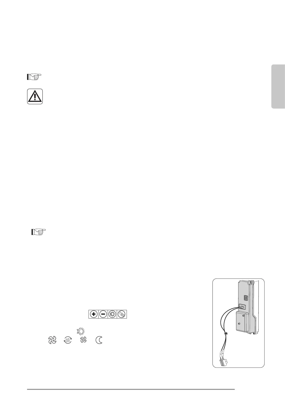
2.12 - CONNECTION WITH WIRED REMOTE CONTROL B0736 OR THIRD PAR-
TIES MODBUS
- Connectthecablescomingfromthe“A B”connectionoftheB0736command
withtherespectivewiresonthemammothconnectedtothepanellid,taking
care to respect the polarity, yellow cord “A” and orange cord “B”, connecting
thefarthestunitwiththe120Ohmresistorsuppliedwiththeappliance.
-
EnableRemoteconguration(paragraph“2.14”,congurationparameter“CF”).
- All the commands “ ” shall be disabled and the message
“rE” will appear on the display every time they are activated.
-
The indicator “ ” showsthechosenmodeofoperation,theindicators
“ ”, “ ”, “ ”, “ ”andthesetfanspeeds
.
- Asregardsthefunctionalitiesandsettings,seetheinstructionsofcommand
B0736.
Bekijk gratis de handleiding van Olimpia Splendid Bi2 Wall TR, stel vragen en lees de antwoorden op veelvoorkomende problemen, of gebruik onze assistent om sneller informatie in de handleiding te vinden of uitleg te krijgen over specifieke functies.
Productinformatie
| Merk | Olimpia Splendid |
| Model | Bi2 Wall TR |
| Categorie | Niet gecategoriseerd |
| Taal | Nederlands |
| Grootte | 30074 MB |


