Olimpia Splendid Bi2 SLIR handleiding
Handleiding
Je bekijkt pagina 32 van 68
GB
F
D
32
I
12
2.6
2.7
2.7.1
13
A A
B
B
CD
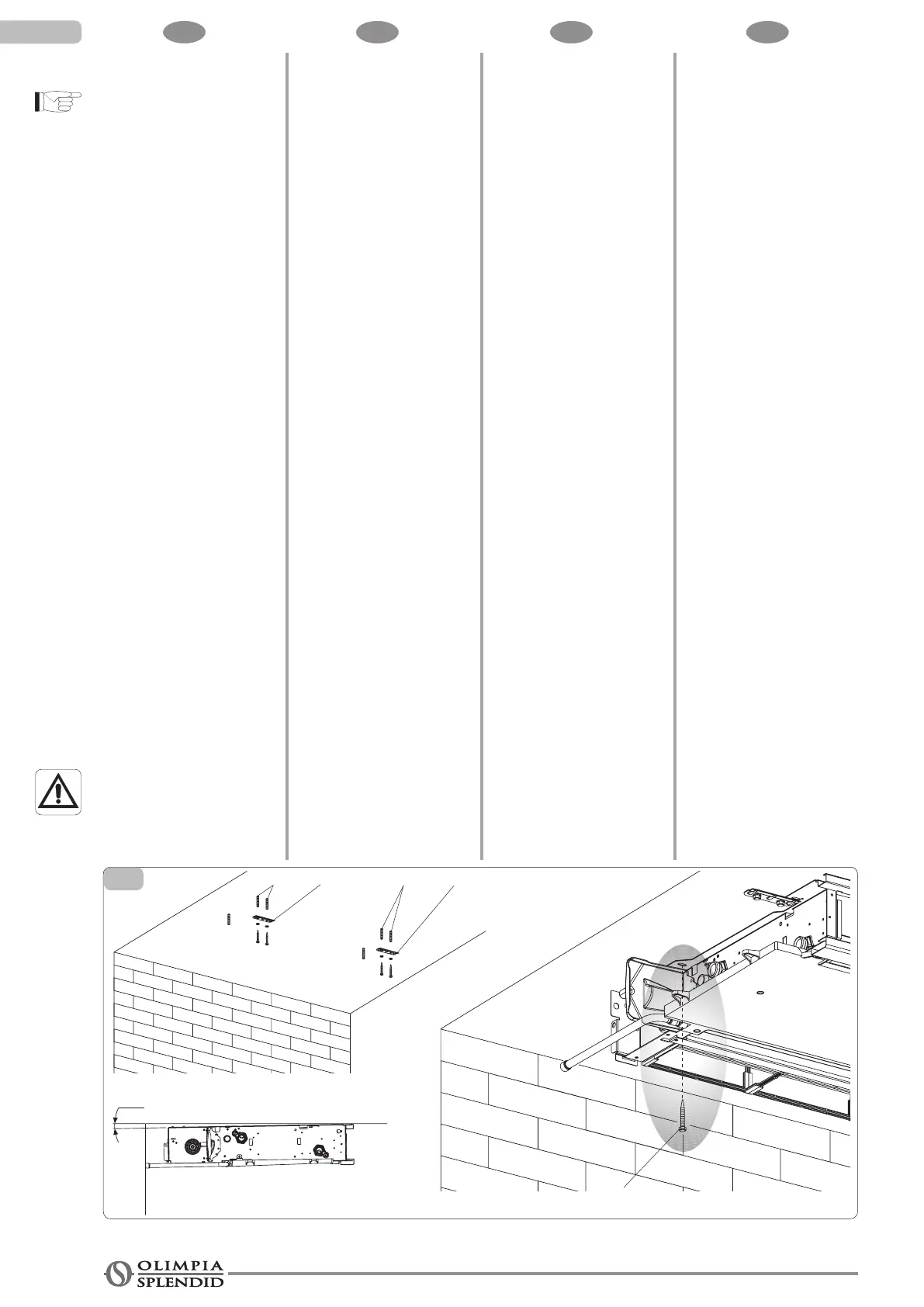
HORIZONTAL OR CEILING
INSTALLATION
This installation is not
permitted for the "Full Flat"
version.
Using the paper template, trace
on the ceiling the position of the
twoxingbracketsandthetwo
rear screws. Using a suitable
drill, make the holes and insert
the toggle bolts (2 for each
bracket)(g.13ref.A);xthe
two brackets (fig. 13 ref. B).
Do not over-tighten the screws.
Position the machine on the two
brackets, keeping it in position
andthenxthetwoscrewsinto
thereartogglebolts(g.13ref.
C), one on each side.
Makesurethatthereissufcient
inclination of the unit towards the
drainage pipe to facilitate the
waterdrainage(g.13ref.D).
Fullytightenall6xingscrews.
HYDRAULIC CONNECTIONS
Pipeline diameter
The minimum internal diameter
that must be respected for
the pipelines of the hydraulic
connections varies according
to the model:
SLI/SLIR/SLR 200 ø12 mm
SLI/SLIR/SLR 400 ø14 mm
SLI/SLIR/SLR 600 ø16 mm
SLI/SLIR/SLR 800 ø18 mm
SLI/SLIR/SLR 1000 ø20 mm
For the position of the pipeline
and the wall fixings, refer
to the designs shown in the
following sections, based on
the specic conguration.
INSTALLATION AU PLAFOND
OU HORIZONTALE
Cette installation n'est pas
permise pour la version "Full
Flat".
Utiliser le gabarit en papier et
tracer au plafond la position des
deuxétriers dexation etdes
deuxvis arrière.Percer avec
unforetappropriéetinsérerles
chevilles(2parétrier)(g.13
réf.A);xerlesdeuxétriers(g.
13réf. B).Ne pas trop serrer
lesvis.
Mettre en place la machine sur
lesdeuxétriers,enlamaintenant
enposition,puisxerlesdeux
visdansleschevillesarrière(g.
13réf.C),uneparcôté.
Ilest conseilléde conférer
une inclinaison appropriée
del’appareil versle tubede
drainagepour faciliterlasortie
del’eau(g.13réf.D).
Serrerdénitivement les6 vis
dexation.
BRANCHEMENTS
HYDRAULIQUES
Diamètre tubes
Le diamètre interneminimum
à respecter pour les tubes des
branchementshydrauliques
varieselonlemodèle:
SLI/SLIR/SLR 200 ø12 mm
SLI/SLIR/SLR 400 ø14 mm
SLI/SLIR/SLR 600 ø16 mm
SLI/SLIR/SLR 800 ø18 mm
SLI/SLIR/SLR 1000 ø20 mm
Pour la position des tubes
pour les prises
murales, voir les dessins
figurant aux paragraphes
suivants, sur la base de la
conguration spécique.
INSTALLATION AN DER
DECKE ODER HORIZONTAL
Bei den "Full Flat" Modellen ist
die horizontale Installation nicht
zulässig.
Verwenden Sie die Papierschablone
und zeichnen Sie an der
Decke die Position der beiden
Befestigungsbügel und der beiden
hinteren Schrauben vor. Bohren
Sie mit einem geeigneten Bohrer
und führen Sie die Dübel ein (2 pro
Bügel) (Abb. 13 Pos. A); Sichern
Sie die beiden Bügel (Abb. 13 Pos.
B). Ziehen Sie die Schrauben nicht
zu fest an
Führen Sie die Maschine auf den
beiden Bügeln ein, wobei Sie die
Position erhalten, und befestigen
anschließend die beiden Schrauben
in den hinteren Dübeln (Abb. 13
Pos. C), jeweils eine pro Seite.
Bitte achten Sie unbedingt auf eine
angemessene Neigung der Einheit in
Richtung des Entwässerungsrohrs,
um das Austreten des Wassers zu
unterstützen (Abb. 13 Pos. D).
Ziehen Sie alle 6
Befestigungsschrauben endgültig
fest.
WASSERANSCHLÜSSE
Durchmesser der
Schlauch-/Rohrleitungen
Der einzuhaltende
Mindestdurchmesser für
die Rohrleitungen der
Wasseranschlüsse ist je nach
Modell unterschiedlich:
SLI/SLIR/SLR 200 ø12 mm
SLI/SLIR/SLR 400 ø14 mm
SLI/SLIR/SLR 600 ø16 mm
SLI/SLIR/SLR 800 ø18 mm
SLI/SLIR/SLR 1000 ø20 mm
Bezüglich der Position der
Schlauch-/Rohrleitungen für
die Wandanschlüsse nehmen
Sie je nach spezifischer
Konguration Bezug auf die in
den nachfolgenden Abschnitten
wiedergegebenen Zeichnungen.
INSTALLAZIONE A SOFFITTO
O ORIZZONTALE
Questa installazione non è
consentita per la versione
"Full Flat".
Utilizzarela dimadi carta,e
tracciareasofttolaposizione
delle due staffedi ssaggio e
delleduevitiposteriori.Forare
con una puntaadeguata ed
infilarei tasselli(2 per ogni
staffa)(g.13 rif.A); ssarele
due staffe (g. 13rif. B).Non
stringereeccessivamenteleviti.
Infilare la macchina sulle
due staffe, mantenendola in
posizionequindi ssareledue
vitineitasselliposteriori(g.13
rif.C),unaperognilato.
Si raccomanda di conferire
un’adeguata inclinazione
dell’unità verso il tubo di
drenaggio per agevolarela
fuoriuscitadell’acqua (fig.13
rif. D).
Stringeredenitivamentetuttele
6vitidissaggio.
COLLEGAMENTI IDRAULICI
Diametro tubazioni
Il diametro interno minimo da
rispettare per le tubazioni dei
collegamentiidraulici variaa
secondodelmodello:
SLI/SLIR/SLR 200 ø12 mm
SLI/SLIR/SLR 400 ø14 mm
SLI/SLIR/SLR 600 ø16 mm
SLI/SLIR/SLR 800 ø18 mm
SLI/SLIR/SLR 1000 ø20 mm
Per la posizione delle
tubazioni per gli attacchi a
parete fare riferimento ai
disegni riportati nei paragra
successivi, in base alla
specica congurazione.
Bekijk gratis de handleiding van Olimpia Splendid Bi2 SLIR, stel vragen en lees de antwoorden op veelvoorkomende problemen, of gebruik onze assistent om sneller informatie in de handleiding te vinden of uitleg te krijgen over specifieke functies.
Productinformatie
| Merk | Olimpia Splendid |
| Model | Bi2 SLIR |
| Categorie | Niet gecategoriseerd |
| Taal | Nederlands |
| Grootte | 17955 MB |


