Nord Modular G2 handleiding
Handleiding
Je bekijkt pagina 231 van 291
NORD MODULAR G2 V1.4x 13. Module reference: Level group
Page 231
The graphic examples shows that the main practical difference between amplitude modulation and
balanced modulation (ringmodulation) is the sideband amplitudes and the appearance of the carrier wave
in the frequency spectrum. When balanced modulation is applied both the carrier frequency and
modulating frequency will disappear completely from the output. Another difference is that the resulting
ring modulation wave phase-shifts 180 degrees (inverts) every half modulator period. If more complex
waveforms are used for amplitude- or ring modulation, sidebands will be generated for each partial of
the wave. See also "Common Level module parameters”. Note that the Mod depth input will make the
output crossfade between the third and the first and the fourth wave graphic in the graphic example.
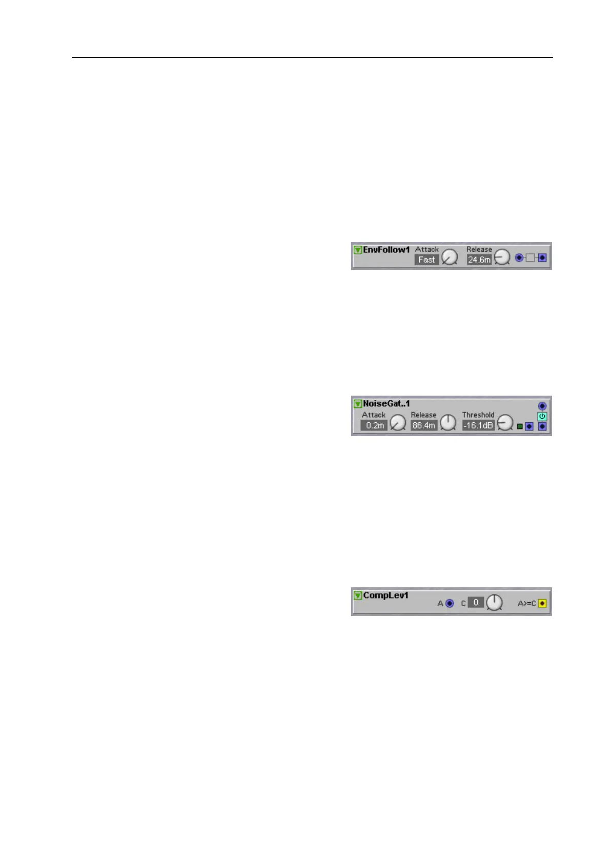
E
NV
F
OLLOW
This module will extract an envelope from a signal,
producing a smoothed control signal on its blue output
that follows the amplitude envelope of an incoming
audio signal. The module has differnt smooth parameters for when the input signal ‘swells’ or ‘decays
out’. Meaning that when the input signal increases in amplitude, the output “follows” the amplitude with
a smoothing rate set by the Attack time. When the input signal amplitude decreases, the output “follows”
the amplitude with a smoothing rate set by the Release time. The input of this module is a D
YNAMIC
C
ONTROL
/A
UDIO
signal input and the output signal is a P
OSITIVE
U
NIPOLAR
control signal. See also
"Common Level module parameters”.
N
OISE
G
ATE
The Noise Gate can be used to “block out” low signal
levels, like faint background noises in a ‘silent’ period in
an external audio signal. When an input signal rises
above the set Threshold value, the gate opens with the
time set with the Attack knob. When the input signal decreases below the set Threshold value, the gate
closes with the set Release time. The
LED
above the output indicates when the input signal is being passed
(
LED
lights up) or being blocked (
LED
is dimmed). The module also has an additional built-in envelope
follower with a separate output for the envelope control signal.
E
NV
O
UTPUT
Outputs a unipolar envelope signal based on the input signal. Signal: P
OSITIVE
U
NIPOLAR
. See also
"Common Level module parameters”.
C
OMP
L
EV
This module produces a logic signal on its yellow output
by comparing a D
YNAMIC
C
ONTROL
/A
UDIO
signal
level to the value set by the knob. If the value of a signal
appearing at the input greater than or equal to the value set in the window, the module produces a logic
HIGH
signal. The logic signal will switch back to
LOW
when the incoming signal drops to a level below the set
value.
L
EVEL
LIMIT
KNOB
Set the level limit for the comparison with the knob. Range: -64 to +64 units. The value is shown in the
Display Box. See also "Common Level module parameters”.
Bekijk gratis de handleiding van Nord Modular G2, stel vragen en lees de antwoorden op veelvoorkomende problemen, of gebruik onze assistent om sneller informatie in de handleiding te vinden of uitleg te krijgen over specifieke functies.
Productinformatie
| Merk | Nord |
| Model | Modular G2 |
| Categorie | Niet gecategoriseerd |
| Taal | Nederlands |
| Grootte | 60689 MB |


