Mitsubishi MSY-GS15NA handleiding
Handleiding
Je bekijkt pagina 6 van 8
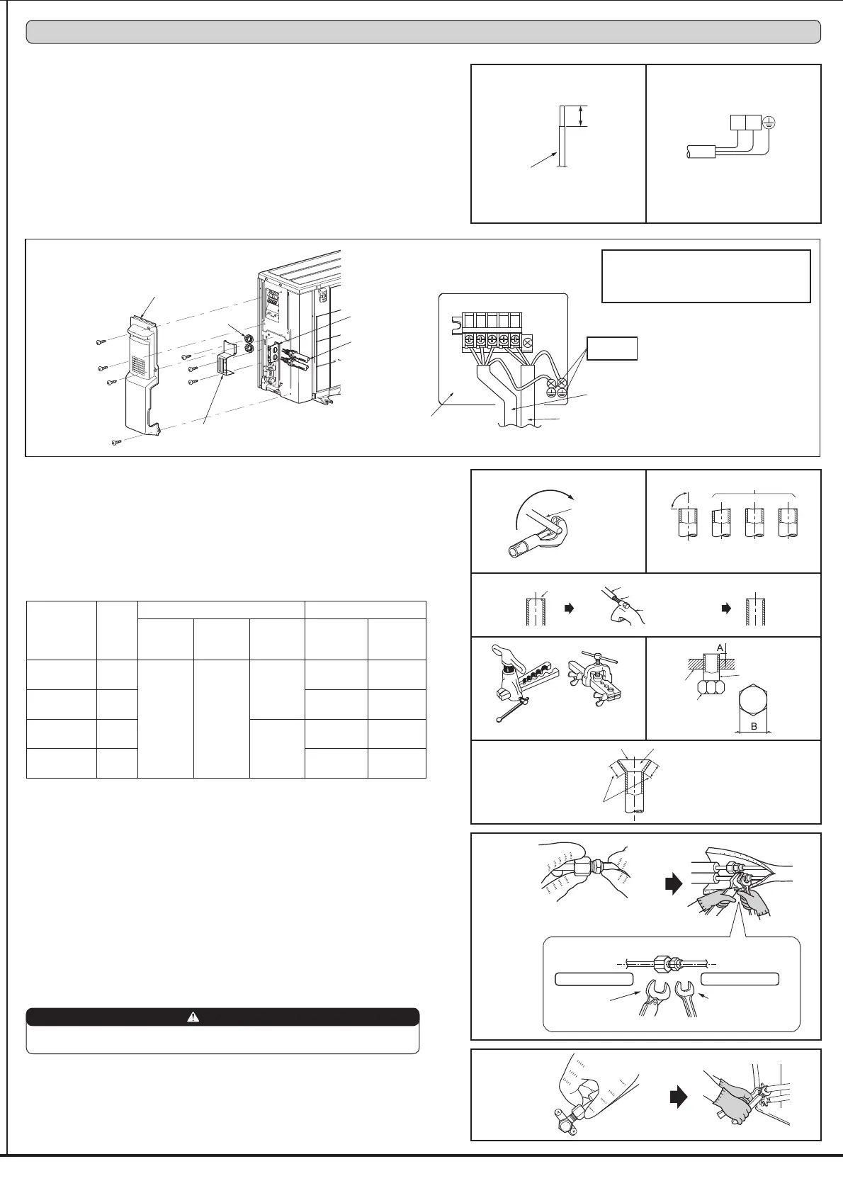
Indoor unit
connection
Outdoor unit
connection
Copper
pipe
Fig. 1
Good
90°
Tilted
No good
Fig. 2
Uneven Burred
Fig. 4
Clutch type
Flaring tool
Wing nut type
Fig. 5
Flare nut
Die
Copper pipe
Smooth all around
Even length all around
Inside is shining without any scratches.
Fig. 6
Flare nut Union joint
External thread sideInternal thread side
7LJKWHQWKHÀDUHQXW
with a torque wrench.
Grip the nut on the
union joint with a spanner.
3-1. CONNECTING WIRES FOR OUTDOOR UNIT
1) Remove the service panel.
2) Remove the conduit cover.
3) Attach the conduit connectors to the conduit plate with lock nuts then secure it against unit with
screws.
4) Connect the ground wires of indoor/outdoor unit connecting wire (A) and power supply cord (K)
to the TB support.
5) Loosen the terminal screws, then attach indoor/outdoor unit connecting wire (A) and power sup-
ply cord (K) from the indoor unit correctly to the terminal block. Attach the wires to the terminal
block securely so that the cores cannot be seen, and no external force affects the connecting
section of the terminal block.
6) Firmly tighten the terminal screws. After tightening, verify that the wires are tightly fastened.
7) Install the conduit cover.
8) Install the service panel securely.
3-2. FLARE CONNECTION
1) Cut the copper pipe as straight as possible with a pipe cutter. (Fig. 1, 2)
2) Remove all burrs from the cut section of the pipe, ensuring that precautions are taken to
avoid getting metal shavings into the piping. (Fig. 3)
5HPRYHÀDUHQXWVDWWDFKHGWRLQGRRUDQGRXWGRRUXQLWVWKHQSXWWKHPRQSLSH
4) Flaring work (Fig. 4, 5). Firmly hold copper pipe in the dimension shown in the table. Select
A inch (mm) from the table according to the tool you use.
5) Check
&RPSDUHWKHÀDUHGZRUNZLWK)LJ
,IÀDUHLVGHIHFWLYHFXWRIIWKHVHFWLRQDQGUHSHDWSURFHGXUH
Lead wire
• Make earth wire a little longer than others.
(More than 3-7/8 in. [100 mm])
• For future servicing, leave some slack in the
connecting wires.
Power supply cord (K)
L1
L2
3-3. PIPE CONNECTION
)DVWHQÀDUHQXWZLWKDWRUTXHZUHQFKDVVSHFL¿HGLQWKHWDEOHUHIHUWR
:KHQIDVWHQHGWRRWLJKWÀDUHQXWPD\HYHQWXDOO\EUHDNDQGFDXVHUHIULJHUDQWOHDNDJH
• Be sure to wrap insulation around the piping. Direct contact with the bare piping may result
in burns or frostbite.
Indoor unit connection
Connect both liquid and gas pipings to indoor unit.
$SSO\DWKLQFRDWRIUHIULJHUDWLRQRLO-RQWKHÀDUHGHQGVRIWKHSLSHV'RQRWDSSO\UH-
frigeration oil on screw threads. Excessive tightening torque will result in damage on the
screw.
7RFRQQHFW¿UVWDOLJQWKHFHQWHUWKHQWLJKWHQWKH¿UVWWRWXUQVRIÀDUHQXWE\KDQG
• Use tightening torque table above as a guideline for indoor unit side joints, and tighten
XVLQJWZRZUHQFKHV([FHVVLYHWLJKWHQLQJGDPDJHVWKHÀDUHVHFWLRQ
Outdoor unit connection
Connect pipes to stop valve pipe joint of the outdoor unit following the same procedure
detailed in Indoor unit connection.
• For tightening, use a torque wrench or spanner.
WARNING
When installing the unit, securely connect the refrigerant pipes before starting
the compressor.
19/32 in.
(15 mm)
Burr
Copper pipe
Spare reamer
Pipe cutter
Fig. 3
3-4. INSULATION AND TAPING
1) Cover piping joints with pipe cover.
2) For outdoor unit side, insulate the piping, including valves.
3) Apply piping tape (G) starting from the connection on the outdoor unit.
• When piping has to be installed through a ceiling, closet or where the temperature and
KXPLGLW\DUHKLJKXVHDGGLWLRQDO¿HOGVXSSOLHGLQVXODWLRQWRSUHYHQWFRQGHQVDWLRQ
Terminal block
Power supply cord (K)
Indoor/outdoor unit
connecting wire (A)
Service panel
Lock nut
Conduit cover
Conduit plate
Conduit pipe
TB support
to conduit cover
3. OUTDOOR UNIT INSTALLATION
Grounding
terminal
Pipe diam-
eter inch
(mm)
B
inch
(mm)
A inch (mm) Tightening torque
Clutch
type tool
for R410A
Clutch
type tool
for R22
Wing nut
type tool
for R22
ft-lb
(kgf•cm)
N•m
ø 1/4 (6.35)
21/32
(17)
0 to 0.02
(0 to 0.5)
0.04 to
0.06
(1.0 to
1.5)
0.06 to
0.08
(1.5 to
2.0)
10 to 13
(140 to 180)
13.7 to 17.7
ø 3/8 (9.52)
7/8
(22)
25 to 30
(350 to 420)
34.3 to 41.2
ø 1/2 (12.7)
1-1/32
(26)
0.08 to
0.10
(2.0 to
2.5)
36 to 42
(500 to 575)
49.0 to 56.4
ø 5/8 (15.88)
1-5/32
(29)
54 to 58
(750 to 800)
73.5 to 78.4
Bekijk gratis de handleiding van Mitsubishi MSY-GS15NA, stel vragen en lees de antwoorden op veelvoorkomende problemen, of gebruik onze assistent om sneller informatie in de handleiding te vinden of uitleg te krijgen over specifieke functies.
Productinformatie
| Merk | Mitsubishi |
| Model | MSY-GS15NA |
| Categorie | Airco |
| Taal | Nederlands |
| Grootte | 1804 MB |


