Mitsubishi MFXZ-KW25-50VG handleiding
Handleiding
Je bekijkt pagina 8 van 12
EN-7
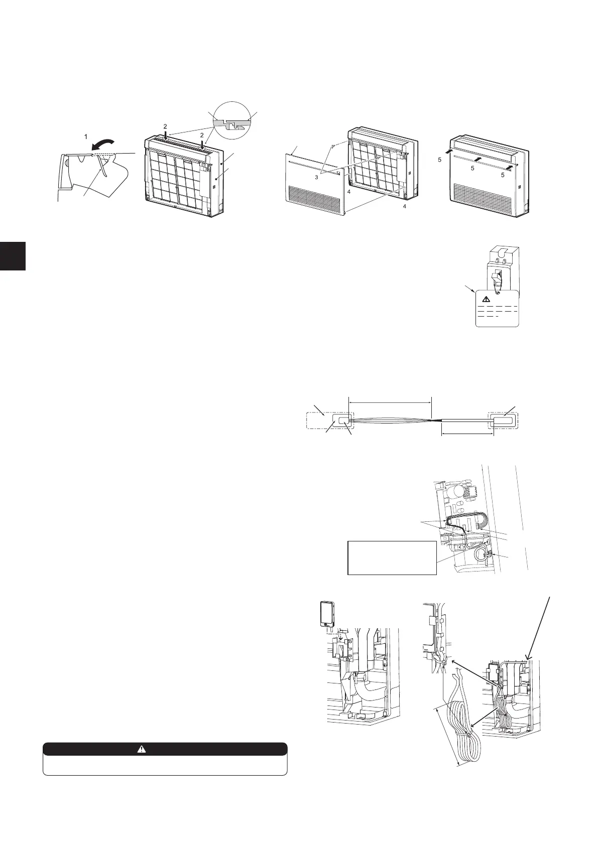
2-8. FRONT PANEL INSTALLATION
1) Open the rear horizontal vane.
2) Attach the panel. Make sure that the catches are engaged.
3) Fix the panel with screws.
4) Insert the bottom part of the front panel.
5) Push 3 places on the upper part of the front panel to close it.
Front panel
Indoor unit
Indoor unit
Panel
Panel
2-10. CONNECTING AN INTERFACE (option)/CONNECTOR CABLE (option) TO THE AIR CONDITIONER
Thin part of the connecting cable.
Place this part where customers
cannot touch it.
Room air
conditioner
Main body of an interface
Thick part of the connecting cable
Indoor control
P.C. board
CN105 for interface
CN104 for connector cable
• Connect an interface/connector cable to the indoor control P.C. board of an
air conditioner with a connecting cable.
• Cutting or extending the connecting cable of the interface/connector cable
results in defects in connecting. Do not bundle the connecting cable together
with power supply cord, indoor/outdoor connecting wire, and/or earth wire.
Keep as much distance as possible between the connecting cable and those
wires.
• The thin part of the connecting cable should be stored and placed where
customers cannot touch it.
Rear horizontal
vane
2-9. HOW TO ATTACH THE LABEL AND THE EXPLANATION
The breaker must be always ON except when performing maintenance or inspection. Hang the accompanying label (14) or
(15) on the breaker, and explain it to customers. When turning the breaker OFF, the power is not supplied to the refrigerant
sensor mounted in the indoor unit, and the refrigerant leakage cannot be detected.
Note: When the wiring is separate indoor unit/outdoor unit power supplies, hang the accompanying label (14) or (15) on the
breaker of indoor unit side, and explain it to customers.
WARNING
(14)
1) Remove the panel.
2) Open the cover of the indoor control P.C. board.
3) Join the connecting cable to CN105 and/or CN104 on the indoor control P.C.
board.
4) Route the connecting cable through this point in the gure.
5) Attach the cable clamp provided with interface/connector cable to the thick
part of the connecting cable with a screw 4 × 16 as shown in the gure.
6) Close the cover of the indoor control P.C. board. Be careful not to catch the
thin part of the connecting cable in the cover. Reinstall the panel.
5)
4)
3) CN105
When mounting the
interface and the connector
cable, use this screw to x
the connecting cable.
3) CN104
WARNING
Fix the connecting cable at the prescribed position securely.
Incorrect installation may cause electric shock, re, and/ or malfunction.
Perform the steps 3) to 5).
Note:
When connecting the Wi-Fi interface (option) Install the interface in the holder
as shown in the gure.
Adjust the length of the cable, and bandle it as shown in the gure.
1) Remove the panel.
2) Open the cover of the indoor control P.C. board.
3) Joint the connecting cable to CN105 on the indoor control P.C. board.
4) Route the connecting cable through this point in the gure.
5) Attach the cable clamp provided with interface/connector cable to the thick
part of the connecting cable with a screw 4 × 16 as shown in the gure.
6) Set the Wi-Fi interface in the holder.
7) Set the connecting cable in the holder, then x it with the band (L).
8) Bundle the excess cable with the band (L). The rolled part should be about
140 mm.
9) Close the cover of the indoor control P.C. board. Be careful not to catch the
thin part of the connecting cable in the cover. Reinstall the panel.
6)
7)
8)
(L)
140
Bekijk gratis de handleiding van Mitsubishi MFXZ-KW25-50VG, stel vragen en lees de antwoorden op veelvoorkomende problemen, of gebruik onze assistent om sneller informatie in de handleiding te vinden of uitleg te krijgen over specifieke functies.
Productinformatie
| Merk | Mitsubishi |
| Model | MFXZ-KW25-50VG |
| Categorie | Airco |
| Taal | Nederlands |
| Grootte | 1832 MB |


