Milwaukee M18 FUEL SURGE handleiding
Handleiding
Je bekijkt pagina 4 van 16
4
Selecting Speed
Allow the tool to come to a complete stop before
changing speeds. Press the selector button to
cycle between the settings.
Setting
Max RPM
1 2 3
2760-20 900 2 100 3 000 Designed for driving
self-tapping screws
in sheet metal
†
†
The function is designed to reduce screw
stripping, screw breakage, and damage to the work
surface when driving self-tapping screws. This func-
tion is optimized for the most common materials,
including #8-#10 self-tapping screws between 1/2"-
1" in length and 20-28 gauge sheet metal.
Starting, Stopping and Controlling Speed
The tool may be operated at any speed from 0 to
full speed.
1. To start the tool, grasp the handle(s) rmly and
pull the trigger.
NOTE: An LED is turned on when the trigger is pulled
and will go o shortly after the trigger is released.
2. To vary the driving speed, increase or decrease
pressure on the trigger. The further the trigger is
pulled, the greater the speed, up to the maximum
speed set by the speed control.
3. To stop the tool, release the trigger and the electric
brake stops the tool instantly. Ensure the tool has
come to a complete stop before laying the tool
down.
Impacting Techniques
The longer a bolt, screw, or nut is impacted, the
tighter it will become. To help prevent damaging the
fasteners or workpieces, avoid excessive impact-
ing. Be particularly careful when impacting smaller
fasteners because they require less impacting to
reach optimum torque.
Practice with various fasteners, noting the length of
time required to reach the desired torque. Check the
tightness with a hand-torque wrench. If the fasteners
are too tight, reduce the impacting time. If they are
not tight enough, increase the impacting time.
Oil, dirt, rust or other matter on the threads or under
the head of the fastener aects the degree of tight-
ness.
The torque required to loosen a fastener averages
75% to 80% of the tightening torque, depending on
the condition of the contacting surfaces.
On light gasket jobs, run each fastener down to a
relatively light torque and use a hand torque wrench
for nal tightening.
Temperature Protection
The tool features internal protections that prevent
damage during extreme cold and overheating.
•
If performance is abnormal in low temperature, pull
the trigger with no load for about 10 seconds to warm
up the tool.
•
In extreme cold temperatures, the tool may shut
down. Allow the tool to warm up before use.
•
If performance is abnormal after heavy use, let
the tool cool down for about 30 minutes. Normal
performance will return.
ASSEMBLY
WARNING
Recharge only with the charger
specied for the battery. For spe-
cic charging instructions, read the operator’s
manual supplied with your charger and battery.
Removing/Inserting the Battery
To remove the battery, push in the release buttons
and pull the battery pack away from the tool.
WARNING
Always lock the trigger or remove
the battery pack any time the tool
is not in use.
To insert the battery, slide the pack into the body
of the tool. Make sure it latches securely into place.
WARNING
Use only sockets and other acces-
sories specifically designed for
use on impact wrenches and drivers. Other
sockets and accessories might shatter or break
causing injury.
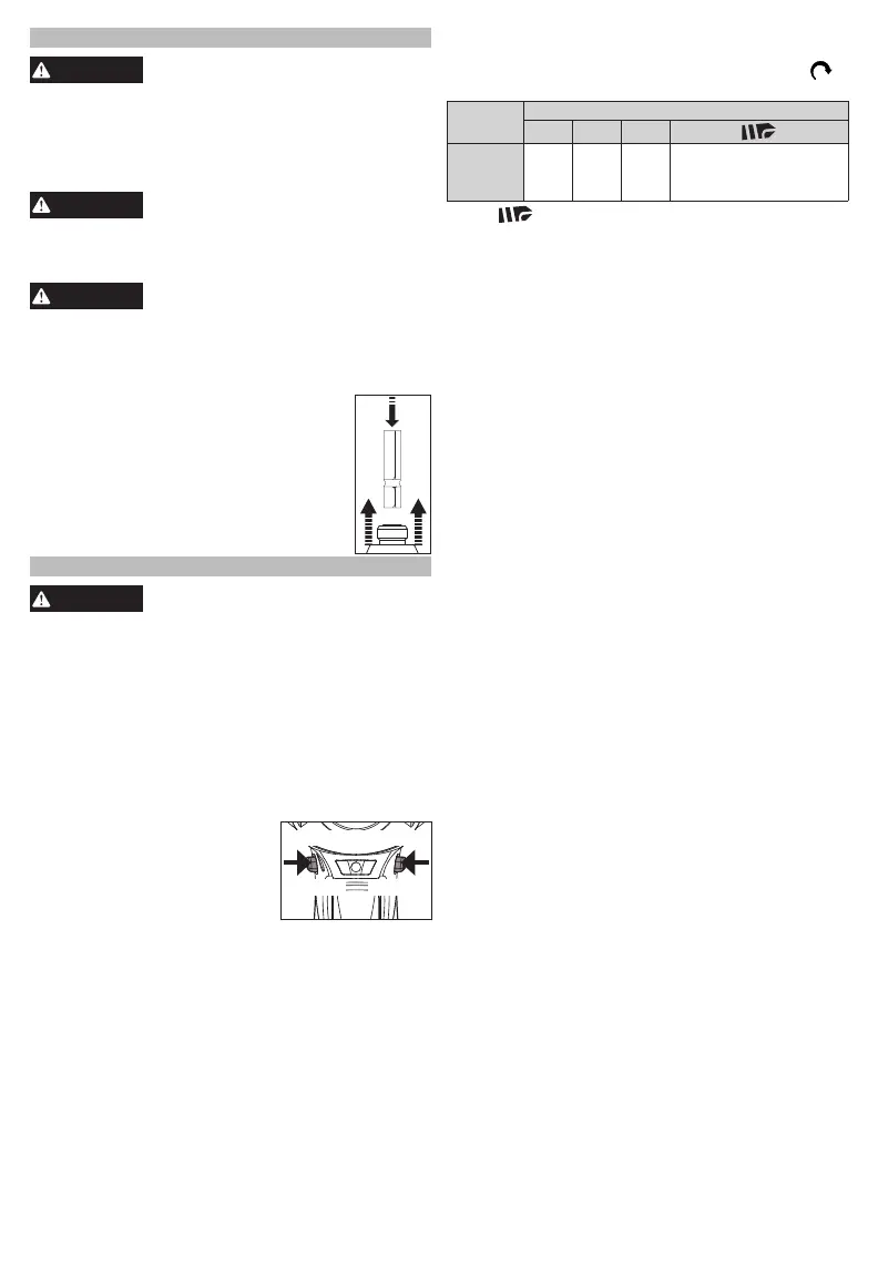
Attaching and Removing Accessories
The tool is intended for use with drill and
driver bits.
1. To attach an accessory, press the
shank into the hex drive chuck.
2. To remove the accessory, pull out the
ring and remove the accessory. Re-
lease the ring.
OPERATION
WARNING
Always remove battery pack before
changing or removing accesso-
ries. Only use accessories specically recom-
mended for this tool. Others may be hazardous.
To reduce the risk of injury, always wear proper
eye protection marked to comply with ANSI Z87.1.
Using the Control Switch
The control switch may be set to three positions:
forward, reverse and lock. Due to a lockout mecha-
nism, the control switch can only be adjusted when
the ON/OFF switch is not pressed. Always allow the
motor to come to a complete stop before using the
control switch.
1. For forward (clockwise) rota-
CENTER TO LOCK
Forward Reverse
tion, push the control switch
in the direction shown. Check
the direction of rotation
before use.
2. For reverse (counterclock-
wise) rotation, push the control switch in the
direction shown. Check the direction of rotation
before use.
3. To lock the trigger, push the control switch to the
center position. The trigger will not work when the
control switch is in the locked position.
Always remove the battery pack before performing
maintenance or changing accessories. Always
lock the trigger or remove the battery pack before
storing the tool and any time the tool is not in use.
Bekijk gratis de handleiding van Milwaukee M18 FUEL SURGE, stel vragen en lees de antwoorden op veelvoorkomende problemen, of gebruik onze assistent om sneller informatie in de handleiding te vinden of uitleg te krijgen over specifieke functies.
Productinformatie
| Merk | Milwaukee |
| Model | M18 FUEL SURGE |
| Categorie | Niet gecategoriseerd |
| Taal | Nederlands |
| Grootte | 2818 MB |


