Handleiding
Je bekijkt pagina 15 van 77
12
0.00
2.00
4.00
6.00
8.00
10.00
12.00
5 10 15 20 25 30 35 40
(b)
(a)
(d)
(c)
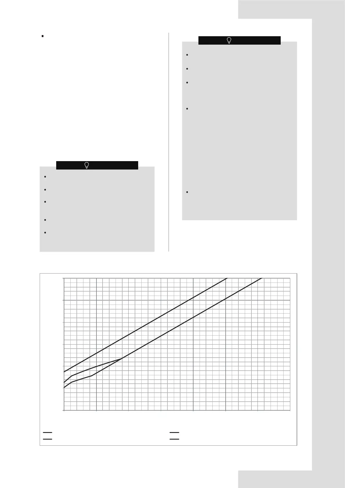
Figure 1-4
For 8-10 kW
Only the factory refrigerant shut-off device can be
used.
The refrigerant shut-off device shall be located
outside.
The refrigerant shut-off device shall only be
installed on the main pipe and is close to the first
branch joint.
The refrigerant shut-off device is not allowed for
series or parallel connections.
The refrigerant shut-off device shall be positioned
to enable access for maintenance by an
authorized person.
Condition B. With additional measure
If the system is equipped with a factory refrigerant
shut-off device on the outdoor unit main pipe and an
alarm device connected to the indoor unit, further rules
regarding refrigerant charge and room area can be
followed. Figure 1-4 and Table 1-4 is suitable for 8-10
kW and Figure 1-5 and Table 1-5 is suitable for
12-18kW.
The alarm device shall be turned on by the
signal from the refrigerant leakage sensor.
The alarm device shall also alert an authorized
person to take appropriate action.
The alarm device shall provide both audible
and visual warnings, such as by a loud (15 dBA
above the background noise level) buzzer and
a flashing light.
At least one alarm device shall be installed
inside each occupied space. For the occupancy
listed below, the alarm system shall also warn
at a supervised location, such as the night
porter’s location, as well as the occupied
space.
Rooms, parts of buildings, buildings where
• sleeping facilities are provided,
• people are restricted in their movement,
• an uncontrolled number of people are
present, or
• to which any person has access without
being personally acquainted with the
necessary safety precautions.
In cases where the alarm device is installed,
the power source of the alarm system shall be
from a power source independent of the
refrigerating systems which the alarm system is
protecting.
(a) Installation height 1 (on the lowest underground floor & A<14 m
2
)
(c) In lowest underground floor (A≥14 m
2
)
(b) Installation height 2 (on the lowest underground floor & A<14 m
2
)
(d) Not in lowest underground floor
Maximum refrigerant charge (Mmax/kg)
Minimum room area (Amin/m
2
)
NOTE
NOTE
1) Curve (a) is the refrigerant charge limitation for the
indoor unit installation height between 1.8 m and
2.2 m while A is < 14 m
2
on the lowest underground
floor.
2) Curve (b) is the refrigerant charge limitation for the
indoor unit installation height not less than 2.2 m
while A is < 14 m
2
on the lowest underground floor.
3) Curve (c) is the refrigerant charge limitation for the
smallest room on the lowest underground floor
while A is ≥ 14 m
2
.
4) Curve (d) is the refrigerant charge limitation for the
smallest room not on the lowest underground floor.
Bekijk gratis de handleiding van Midea V8M-160WV2N8, stel vragen en lees de antwoorden op veelvoorkomende problemen, of gebruik onze assistent om sneller informatie in de handleiding te vinden of uitleg te krijgen over specifieke functies.
Productinformatie
| Merk | Midea |
| Model | V8M-160WV2N8 |
| Categorie | Airco |
| Taal | Nederlands |
| Grootte | 11133 MB |


