Handleiding
Je bekijkt pagina 10 van 20
Manufacturer reserves the right to change, at any time, specifications and designs without notice and without obligations.
10
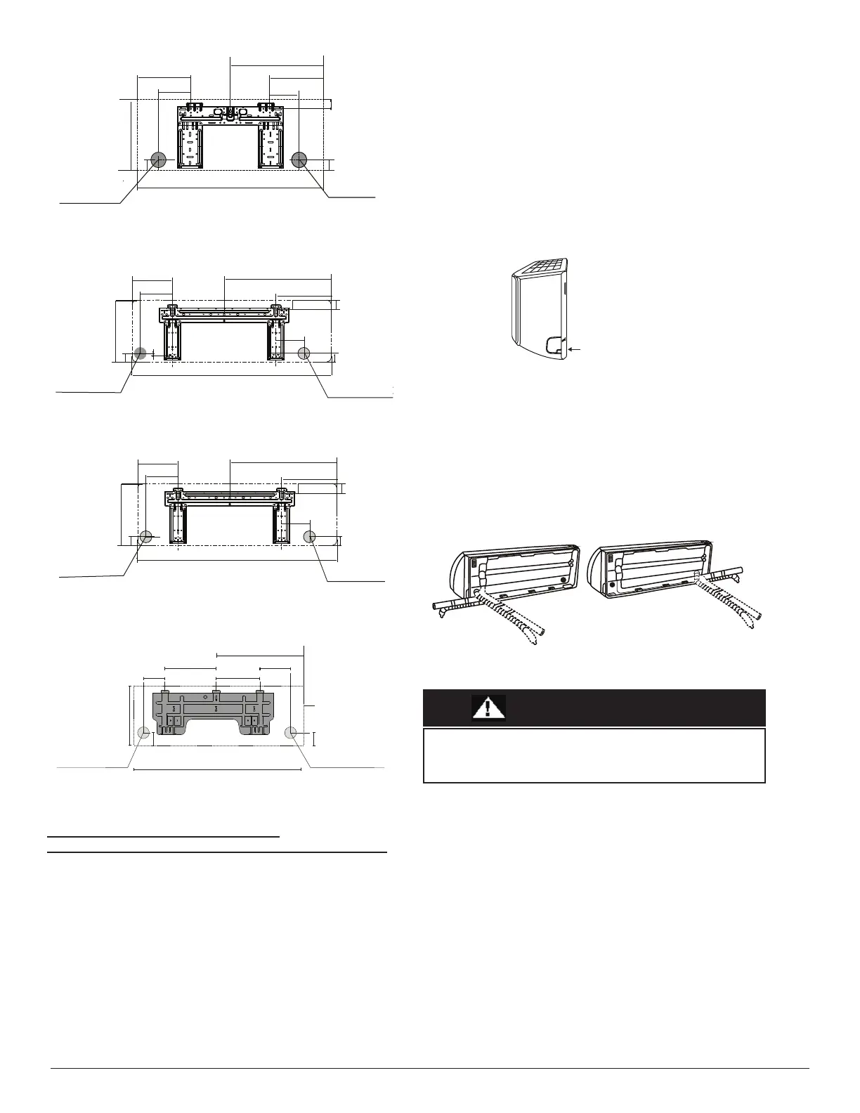
Fig. 12 — 12K Models
Fig. 13 — 18K Models
Fig. 14 — 24K Models
Fig. 15 — 30K and 36K Models
DRILL A HOLE IN WALL FOR THE
INTERCONNECTING PIPING, DRAIN AND WIRING
Refrigerant Line Routing
The refrigerant lines may be routed in any of the four directions. For
maximum serviceability, it is recommended to have refrigerant line
flare connections and the drain connections on the outside of the wall
that the fan coil can be mounted on. If piping is going through the
back, determine the pipe hole position using the mounting plate as a
template. Drill pipe hole diameter per values given in figures 11
through 13. The outside pipe hole is 1/2−in. (13 mm) min. lower than
the inside pipe hole, so it slants slightly downward.
Step 5 - Prepare Refrigerant Piping
The refrigerant piping is inside an insulating sleeve attached to the
back of the unit. The installer must prepare the piping before passing
it through the hole in the wall.
1. Based on the position of the wal
l hole relative to the mounting
plate, choose the side from which the piping exits the unit.
2. If the wall hole is behind the unit, keep the knock-out panel in
place. If the wall hole is to the side of the indoor unit, remove the
plastic knock-out panel from that side of the unit. This creates a slot
through which your piping can exit the unit. Use needle nose pliers
if the plastic panel is too difficult to remove by hand.
Fig. 16 — Knock-out Panel
3. If the existing connective piping is already embedded in the wall,
proceed directly to “Step 6 - Connect the Drain Hose”. If there is no
embedded piping, connect the indoor unit’s refrigerant piping to the
connective piping that connects the indoor and outdoor units.
NOTE: Refrigerant piping can exit the indoor unit from
four different angles; left-hand side, right-hand
side, left rear, right rear.
Fig. 17 — Piping Angles
Left rear wall
hole 2.5in (65mm)
Right rear wall
hole 2.5in (65mm)
9.1in(230mm)
31.7in (805mm)
9.1in(231mm)
15.9in (403mm)
11.7in(297mm)
1.8in(47mm)
1.4in
(36mm)
2.1 in
53mm)
190mm(7.5in)
4.8in(121mm)
Left rear wall
hole 2.5in (65mm)
Right rear wall
hole 2.5in (65mm)
6.5in(165mm)
20.7in(527mm)
9.7in(247mm)
4.2in(106mm)
1.9in(48mm)
1.1in(29mm)
2.1in
(37mm)
5.5in
(139mm)
38.2in(971mm)
12.6in (321mm)
1.9in
(48mm)
Left rear wall hole
3.54in (90mm)
Right rear wall hole
3.54In(90mm)
7.8in(199mm)
23.7in(603mm)
12.7in(322mm)
5.1in(129mm)
2.2in
(55mm)
2.1in
(54mm)
2.1in
(54mm)
6.8in
(173mm)
42.6in(1082mm)
13.3in(337mm)
6.8in(172mm)
14.25in(362mm)
Left rear wall
hole 3.54in(90mm)
Right rear wall
hole 3.54in(90mm)
49.55in(1259mm)
Indoor unit outline
2.05in(52mm)
15.3in(389mm)
13.05in(332mm)
10.1in(257mm)
25.3in(643.6mm)
2.05in (52mm)
Knock-out Panel
Be extremely careful not to dent or damage the piping while
bending them away from the unit. Any dents in the piping will
affect the unit’s performance.
CAUTION
Bekijk gratis de handleiding van Midea MASAG18-21HS2G, stel vragen en lees de antwoorden op veelvoorkomende problemen, of gebruik onze assistent om sneller informatie in de handleiding te vinden of uitleg te krijgen over specifieke functies.
Productinformatie
| Merk | Midea |
| Model | MASAG18-21HS2G |
| Categorie | Airco |
| Taal | Nederlands |
| Grootte | 3297 MB |


