Microchip MPF050TL handleiding
Handleiding
Je bekijkt pagina 7 van 102
DC Characteriscs
Data Sheet
© 2024 Microchip Technology Inc. and its subsidiaries
DS00003831E - 7
4. DC Characteriscs
This section lists the DC characteristics of the PolarFire FPGA device.
4.1 Absolute Maximum Rang
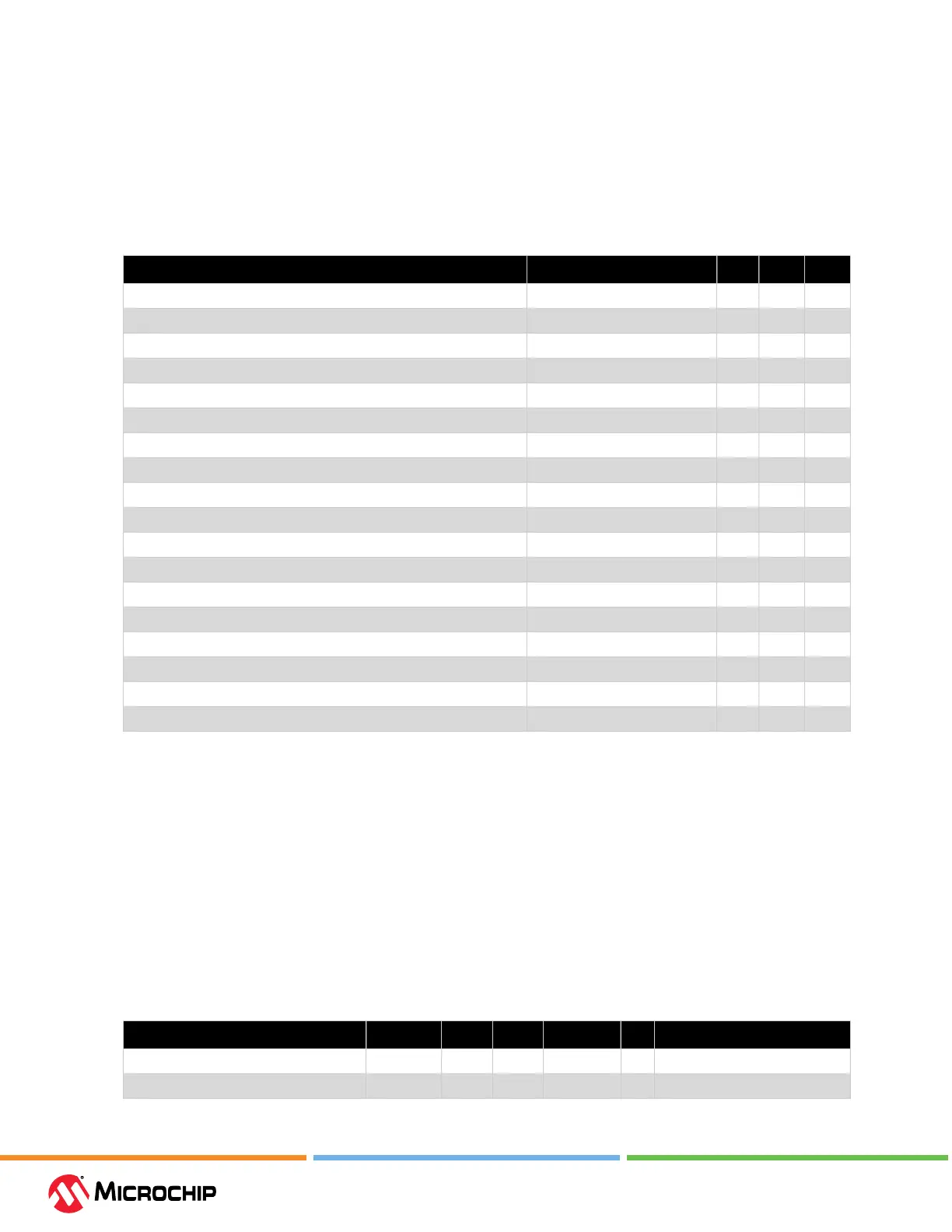
The following table lists the absolute maximum ratings for PolarFire devices.
Table 4-1. Absolute Maximum Rang
3
Parameter Symbol Min Max Unit
FPGA core power supply V
DD
–0.5 1.13 V
Transceiver Tx and Rx lanes supply V
DDA
–0.5 1.13 V
Programming and HSIO receiver supply V
DD18
–0.5 2.0 V
FPGA core and FPGA PLL high-voltage supply V
DD25
–0.5 2.7 V
Transceiver PLL high-voltage supply V
DDA25
–0.5 2.7 V
Transceiver reference clock supply V
DD_XCVR_CLK
–0.5 3.6 V
Global V
REF
for transceiver reference clocks XCVR
VREF
–0.5 3.6 V
HSIO DC I/O supply
2
V
DDIx
–0.5 2.0 V
GPIO DC I/O supply
2
V
DDIx
–0.5 3.6 V
Dedicated I/O DC supply for JTAG and SPI V
DDI3
–0.5 3.6 V
GPIO auxiliary power supply for I/O bank x
2
V
DDAUXx
–0.5 3.6 V
Maximum DC input voltage on GPIO V
IN
–0.5 3.8 V
Maximum DC input voltage on HSIO V
IN
–0.5 2.2 V
Transceiver receiver absolute input voltage Transceiver V
IN
–0.5 1.26 V
Transceiver reference clock absolute input voltage Transceiver REFCLK V
IN
–0.5 3.6 V
Storage temperature (ambient)
1
T
STG
–65 150 °C
Junction temperature
1
T
J
–55 135 °C
Maximum soldering temperature RoHS T
SOLROHS
— 260 °C
1. See Table 5-67. FPGA and μPROM Programming Cycles vs. Retention Characteristics for retention
time vs. temperature. The total time used in calculating the device retention includes the device
operating temperature time and temperature during storage time.
2. The power supplies for a given I/O bank x are shown as V
DDIx
and V
DDAUXx
.
3. Absolute maximum ratings are stress ratings only; functional operation of the device at these
or any other conditions beyond those listed under the recommended operating conditions
specied in Table 4-2. Recommended Operating Conditions is not implied. Stresses beyond
those listed in the following table might cause permanent damage to the device. Exposure to
absolute maximum rating conditions for extended periods may aect device reliability.
4.2 Recommended Operang Condions
The following table lists the recommended operating conditions.
Table 4-2. Recommended Operang Condions
Parameter Symbol Min Typ Max Unit Condition
FPGA core supply at 1.0V mode
1, 6
V
DD
0.97 1.00 1.03 V —
FPGA core supply at 1.05V mode
1, 6
V
DD
1.02 1.05 1.08 V —
Bekijk gratis de handleiding van Microchip MPF050TL, stel vragen en lees de antwoorden op veelvoorkomende problemen, of gebruik onze assistent om sneller informatie in de handleiding te vinden of uitleg te krijgen over specifieke functies.
Productinformatie
| Merk | Microchip |
| Model | MPF050TL |
| Categorie | Niet gecategoriseerd |
| Taal | Nederlands |
| Grootte | 18409 MB |


