Martin VC-Strip handleiding
Handleiding
Je bekijkt pagina 19 van 36
System installation 19
To create a DMX-controlled installation that draws DC power from a generic PSU:
1. See Figure 8 on page 18 for an overview of this type of installation.
2. Make sure that no devices in the installation can be connected to AC mains power until all installation
work is complete.
3. Read ”Safety information” starting on page 4 and “Precautions to avoid damage” on page 7.
4. Connect VC-Strips together in chains using Martin hybrid PCB-to-PCB cables (see ”VC-Strip to VC-Strip
link cables” on page 31). Connect each cable from the THRU connector on one VC-Strip to the IN
connector on the next VC-Strip.
Warning! Check the PSU’s DC output power rating in watts and the power consumption figures in watts
for VC-Strip modules given in Table 3 on page 6. Do not create a chain of VC-Strip modules that will
exceed the power rating of the DC output on the PSU. Even if the PSU’s DC output power rating would
be high enough, do not create a chain of VC-Strips that contains more than the maximum permitted
number per chain given in Table 3 on page 6.
5. See Figure 9. Connect a Martin hybrid-to-PCB adapter cable (P/N 91616035) to the first VC-Strip of
each chain.
6. If necessary, you can extend the hybrid link cable run by connecting a Martin 4-pin XLR hybrid extension
cable to the Hybrid-to-PCB adapter cable. Suitable extension cables are available from Martin in various
lengths. See ”Extension cables” on page 31.
7. See Figure 9. If the PSU does not have constant overcurrent protection that will limit current to 8 A on
the DC output used, install an inline fuseholder with a 7.5 A or 8 A fuse on the white (+ve) power wire of
a Martin hybrid lead-in cable (P/N 91616037). A 30 amp automotive-type inline fuseholder with a 7.5 A
blade fuse can be used. Connect the power wires on the lead-in cable to a DC output on the PSU.
Connect the white wire to positive (+ve) and the black wire to negative (-ve).
8. Connect the 4-pin female XLR connector on the hybrid lead-in cable to the 4-pin male connector on the
hybrid-to-PCB adapter cable (or on the hybrid extension cable, if you have extended the hybrid link).
9. Connect the 5-pin male XLR connector on the hybrid lead-in cable to a DMX link that carries a DMX
signal from an RDM-compliant DMX controller.
10. Apply AC mains power to the external PSU.
11. Apply AC mains power to the DMX controller.
You can now configure the system. See ”System setup”on page 21.
Connecting additional devices to a VC-Strip chain
Drawing off combined data and DC power from the end of a chain
If you want to continue the hybrid link to carry 48 VDC power and a P3 video or DMX signal from the end of
a VC-Strip chain to other devices, connect a Martin Hybrid Adapter Cable, PCB to 4-pin female XLR, P/N
91616036, to the OUT connector of the last module in the chain.
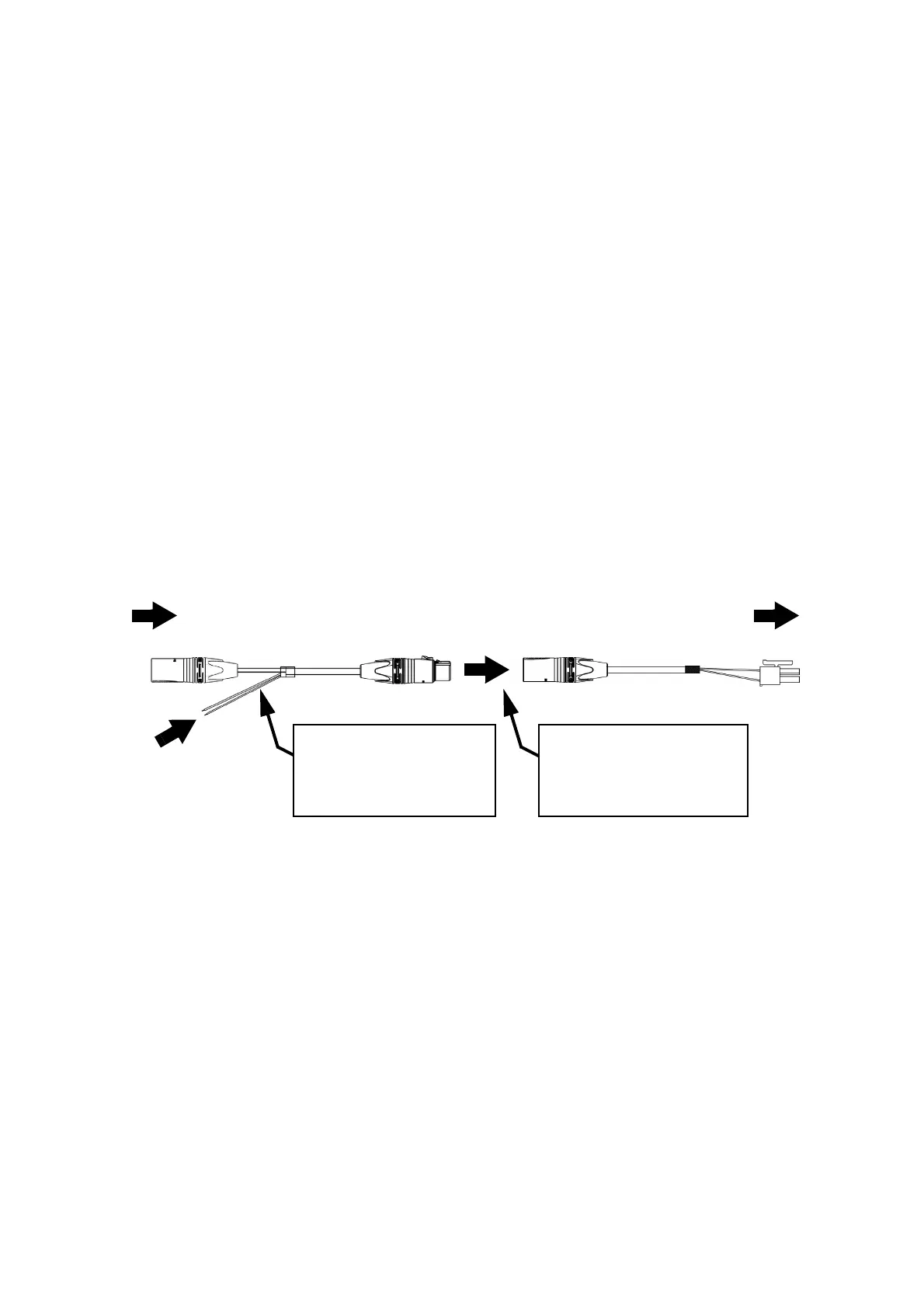
Figure 9: Generic PSU and DMX connections to a VC-Strip chain
DC power from
white to +ve, black to -ve
To VC-Strip
Hybrid DC lead-in cable, P/N 91616037
chain
5-pin male XLR 4-pin female XLR
4-pin male XLR PCB connector
Hybrid-to-PCB adapter cable, P/N 91616035
generic 48 VDC PSU
Insert 4-pin XLR hybrid
extension cable here if you
need to extend the cable run
Insert 7.5 A or 8 A inline
fuse here if PSU does not
have 8 A overcurrent
protection
DMX from DMX/RDM
controller
Bekijk gratis de handleiding van Martin VC-Strip, stel vragen en lees de antwoorden op veelvoorkomende problemen, of gebruik onze assistent om sneller informatie in de handleiding te vinden of uitleg te krijgen over specifieke functies.
Productinformatie
| Merk | Martin |
| Model | VC-Strip |
| Categorie | Niet gecategoriseerd |
| Taal | Nederlands |
| Grootte | 3742 MB |


