Martin VC-Strip 15 handleiding
Handleiding
Je bekijkt pagina 12 van 36
12 VC-Strip™ Family Safety and Installation Guide
System installation
Warning! Read “Safety information” on page 4 and “Precautions to avoid damage” on page 7
carefully before installing a VC-Strip system.
Warning! Connect the VC-Strip only to the devices and using only the Martin cables specified in this
manual.
Warning! Do not exceed the maximum numbers of devices that can be connected in chains and
maximum cable lengths specified in ”Protection from electric shock” starting on page 4 and in the
manuals of the other devices in the system.
Important! The VC-Strip is not designed to allow hot-plugging. Shut down power and data before
connecting or disconnecting modules.
The VC-Strip is designed to display either Martin P3 video or DMX-controlled lighting effects. It
automatically recognizes and responds to either a Martin P3 or a DMX data signal. The next sections
explain how to create a VC-Strip installation to display P3 video data or DMX-controlled lighting effects.
Installing a P3 system
See Figure 5 for an overview of the layout of a Martin P3 video display system that uses a P3 PowerPort
1500.
The P3 link requires Ethernet Cat 5e or better network cable. The cable run between any two devices on the
link can be up to 100 m (328 ft.) in length. If necessary, a cable run can be extended beyond 100 m by
inserting an unmanaged Ethernet switch or using a fiber-optic system (see the P3 system controller user
manual for details).
To install a system that displays P3 video on VC-Strips, see the overview in Figure 5 and follow these
directions:
1. Make sure that no devices in the installation can be connected to AC mains power until all installation
work is complete.
2. Read “Safety information” on page 4 and “Precautions to avoid damage” on page 7.
3. Connect VC-Strip modules together in chains using Martin hybrid PCB-to-PCB cables (see ”VC-Strip to
VC-Strip link cables” on page 31). Connect each cable from the THRU connector of one VC-Strip to the
IN connector of the next VC-Strip to create the chain.
Warning! Do not exceed the maximum permitted number of modules per chain given in Table 1 on
page 5.
4. Connect each chain of VC-Strips to one of the four 4-pin female XLR hybrid (48 VDC power + P3 data)
outputs on the Martin P3 PowerPort 1500 using a Martin hybrid 4-pin male XLR to PCB adapter cable,
P/N 91616035 (see Figure 4).
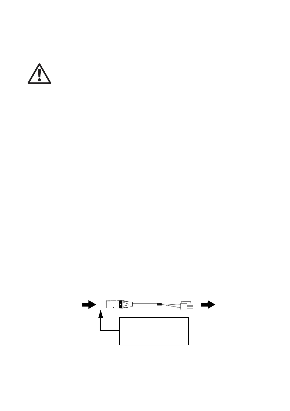
Figure 4: Power and P3 video data input from P3 PowerPort 1500
4-pin male XLR PCB connector
4-pin XLR Hybrid-to-PCB adapter cable, P/N 91616035
Insert 4-pin XLR hybrid
extension cable here if you
need to extend the hybrid cable
run
DC power and
data from P3
PowerPort 1500
DC power and
data to VC-Strip
chain
Bekijk gratis de handleiding van Martin VC-Strip 15, stel vragen en lees de antwoorden op veelvoorkomende problemen, of gebruik onze assistent om sneller informatie in de handleiding te vinden of uitleg te krijgen over specifieke functies.
Productinformatie
| Merk | Martin |
| Model | VC-Strip 15 |
| Categorie | Niet gecategoriseerd |
| Taal | Nederlands |
| Grootte | 3742 MB |


