Martin Audio MA4.2s handleiding
Handleiding
Je bekijkt pagina 5 van 21
Martin Audio – MA4.2s Amplifier
ENGLISH
5
6 . On in dica tor
T p5-he two bo tto m gree n L ED ’s in dicate tha t th e o utp ut circuits are re ceivin g th e corre ct ra il vo lta ge .
7 . Fa n g rille filte rs
T wo g rille s w ith fo a m filte rs a re lo cated o n the fron t p an el to p re ven t d ust fro m en terin g the a m plifie r. Th e g rille s are
rem ovab le fo r e asy cle an ing o f the filters b y sim ply pu lling th em o ff. T h e fo am filte rs sho u ld a lwa ys b e u se d .
8 . Po we r s witch
T urns m a in s p ow er o n o r o ff.
(See page 10 and 14
)
9 . AC in dica tor
Ind icate s if AC voltag e is prese nt. N ote: th is in dica to r is located electrica lly in fro nt o f the po we r switch .
1 0. A FS in dic ator
Ind icate s if th e AF S (Au tom atic Fu se Sa ve r) -curren t lim iter is a ctiva te d .
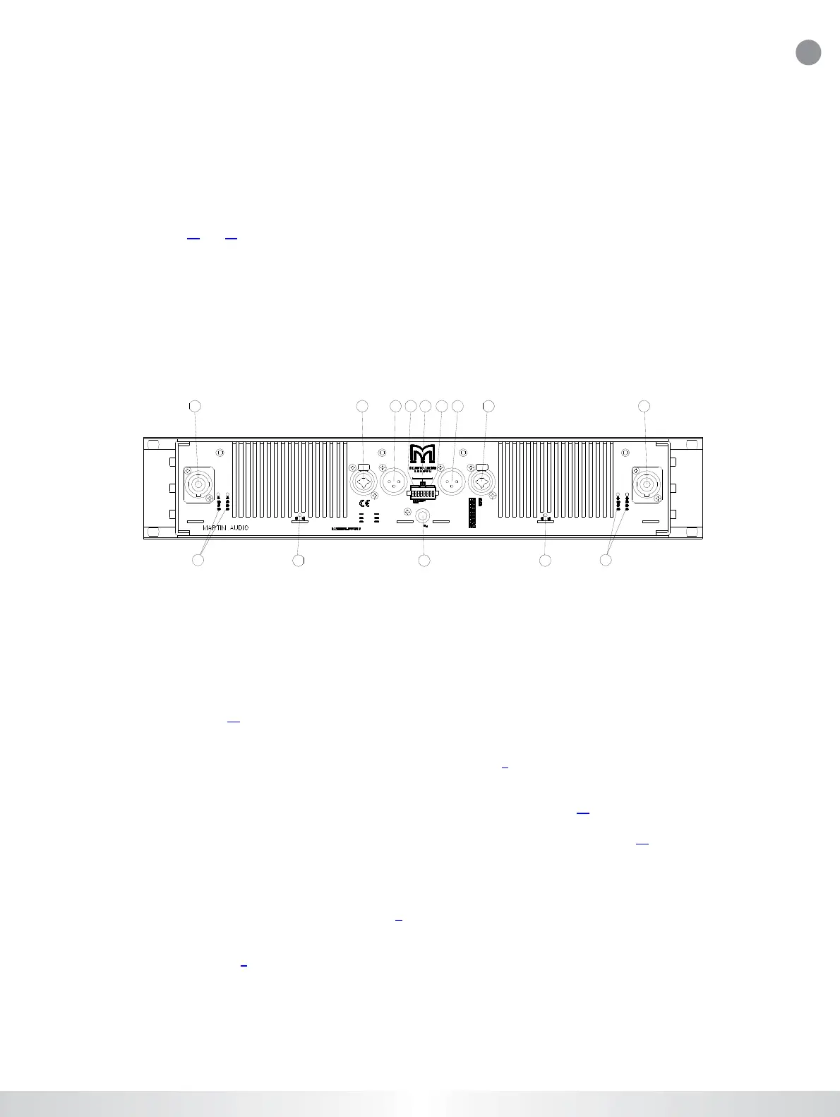
4.3 Rear Panel
CH. B
CH . A
INPUT
INPUTCH . A L INK
CH.B LINK
GAIN
41dB
38dB
35dB
32dB
29dB
26dB
23dB
20dB
678
123
GAI N
CH.B
GAI N
CH . A
LINK/ BRIDGE A+B
ON
OFF
Cu rrent consumpt ion: 7.8A
230-240V 50-60Hz
1+ CH.B+
1- CH.B-
Ser. No :
OUTPUT CH.A
Cli p Lim it er A
On
Of f
STEREO
1+CH.A+
1- CH .A-
2+CH.B+
2- CH.B-
BRIDGE
Pin 1+ Spk +
2- Spk-
Pa t en t s
SE 9 0 03426
EP 0483094
US 5200711
Clip Limiter B
On
O
ff
0
-2
-4
-5
MLS swit ch
dB
MLS switch
dB
OUTPUT CH. B
STEREO
Mus t be gro unded
XLR
Pin 1 Scrn Sleeve
2 Pos Tip
3 Neg Ring
1/ 4“
Made in the EEC by
MA 4.2s
-2
-5
-4
0
145678541
393
2 2
1. Output / Speaker connector
T he S pe akon co nn e ctor from N eu trik ma y b e un fa m ilia r to so m e use rs. A full d escrip tio n is fo un d in the o pe ratio n
section . (Se e p ag e 1 3).
2. Minimum load selector (MLS™) switch
These switches are used to select the maximum output power. (See page 8).
3. Clip limiter switch
Turns the clip limiter “ON” (switch IN position) or “OFF” (switch OUT position). (See page 15).
4. Input signal XLR. Neutrik Combijack features also _” TRS phone jacks. (Pin 2 is “hot”, see page 12).
5. Link Input. XLR male connector connected in parallel to the female for linking the channel to another input.
6. Gain switch channel B. Three of the switches in the DIP-switch selects the maximum gain of the channel to be
either 20, 23, 26, 29, 32, 36, 39 or 41 dB. (See page 6).
7. Link and Polarity reverse switch. Two of the switches in the DIP-switch are used for Link and Bridge
operation. (See page 7).
8. Gain switch channel A. Three of the switches in the DIP-switch selects the maximum gain of the channel to be
either 20
,
23
,
26
,
29
,
32
,
36
,
39 or 41 dB.
(
See
p
a
g
e 6
)
.
All material © 2007. Martin Audio Ltd. Subject to change without notice.
CONTENTS
<
>
PRINT
GUIDES
Bekijk gratis de handleiding van Martin Audio MA4.2s, stel vragen en lees de antwoorden op veelvoorkomende problemen, of gebruik onze assistent om sneller informatie in de handleiding te vinden of uitleg te krijgen over specifieke functies.
Productinformatie
| Merk | Martin Audio |
| Model | MA4.2s |
| Categorie | Niet gecategoriseerd |
| Taal | Nederlands |
| Grootte | 3550 MB |


