Liberty Pumps XLSGX200 handleiding
Handleiding
Je bekijkt pagina 7 van 12
6850000E Copyright © Liberty Pumps, Inc. 2022
All rights reserved. 7 | EN
Prepa ration
Always disconnect pump(s) from power source(s) before
handling or making any adjustments to either the pump(s),
the pump system, or the control panel.
Prepare Sump [Basin]
If replacing a previously installed pump, prepare the basin by
removing the old pump and cleaning any debris from the basin.
Inspect all remaining equipment in the basin including guide rails,
piping, valves, and electrical junction boxes (if present) and repair
or replace as appropriate. Ensure that control hardware such as
floats or pressure transducers are clean, properly adjusted, and in
good working order.
Pump installation should be at a sufficient depth to ensure that all
plumbing is below the frost line. If this is not feasible, remove the
check valve and size the basin and/or adjust pump differential to
accommodate the additional backflow volume. Consult Liberty
Pumps for details on how this should be done.
Pump Control and Alarm Floats
The water level in the basin is determined by the placement of the
control floats and should be positioned such that the motor
housing is completely submerged to properly cool the motor. If
full submersion is not possible, the minimum water depth must be
no less than 13
inches as measured from the bottom of the pump
legs. The upper water level should be positioned to minimize
pump starts. The alarm float must be above the turn-on float
switch but below any inlets. No control should be set above the
inlet to the basin.
Set the second (turn-on) control above the lower turn-off control.
The exact distance between the two floats must be a compromise
between a frequent pumping cycle (10 starts per hour max) to
properly manage sewage level, and a longer pump run duration
per start, which maximizes energy efficiency. This distance must be
determined by the engineer, depending on the conditions of the
application.
Cutter and Impeller Free Movement Check
Wear Personal Protective Equipment to protect hands as
cutter blades have extremely sharp edges and present a
serious cutting hazard.
Do not connect any power to pump until this check is complete.
Manually rotate the cutter to check that it spins freely with very
little resistance. The cutter is located on the bottom of the pump.
The cutter can be carefully rotated by hand, or rotated by inserting
a tool into the cutter bolt. If rotating by hand, wear protective
gloves as the cutter and cutter plate have sharp edges. The pump
can remain upright or can be laid down on its side for easier access
to the cutter. Besides verification that the cutter and impeller are
freely spinning, rotating the cutter helps to lubricate the shaft seals
if the pump has been non-operational for more than a week. It is
recommended to rotate the cutter 5–10 full rotations.
Installa tion
All installation and maintenance of pumps, controls,
protection devices, and general wiring shall be done by
qualified personnel.
All electrical and safety practices shall be in accordance with
the National Electrical Code
®
, the Occupational Safety and
Health Administration, or applicable local codes and
ordinances.
For pressure sewer applications, verify a Redundant Check
Valve Assembly (curb stop and check valve) is installed
between the pump discharge and the street main, as close to
the public right-of-way as possible, on all installations to
protect from system pressures.
Electrical Connections
With mains power disconnected, complete pump and control
wiring connections per wiring diagrams included with the control
panel and
Figure 1/Figure 2 as applicable. All wires should be
checked for unintentional grounds with an ohmmeter after the
connections are made.
3-Phase Pump Rotation Verification
Check 3-phase pumps for correct rotation prior to installing
pump(s) in basin. To change rotation, reverse any two of the
three power leads to the pump (not the ground). Code the
wires for reconnection after installation.
3-phase power uses three separate
alternating currents that peak at different
integrals. With pumps that are powered
by three phase electric, the phase
sequence of the motor must match the
phase sequence of the power source.
When the phase sequences match, the
pump operates properly. However, when
the phases are out of order, the pump
runs backward (i.e., the impeller rotates in
the wrong direction). This causes an
extreme loss of performance and could
raise the current draw, which could result in tripping an overload
or circuit breaker.
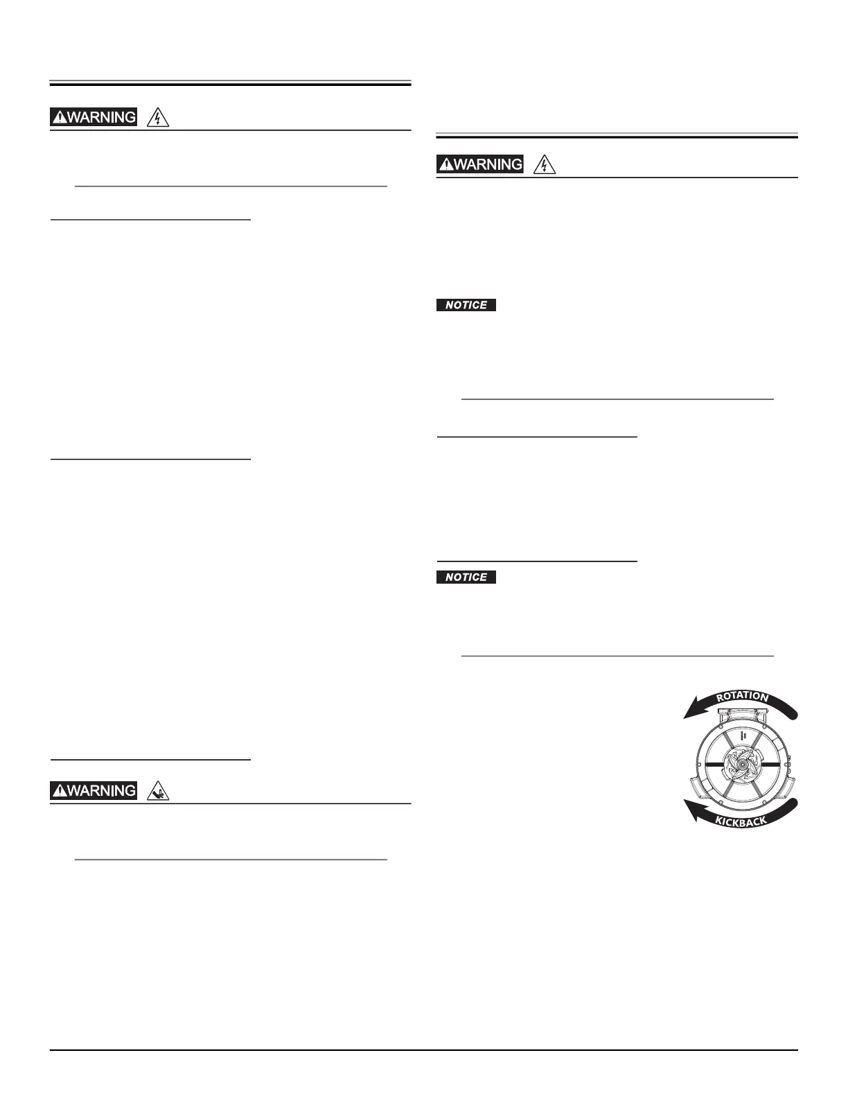
To ensure that the power to the pump is installed correctly, always
verify proper rotation before lowering it into the basin. If the pump
is rotating in the wrong direction, turn off the power and reverse
any two power leads. This reverses the phase sequence and
corrects the pump rotation. Rotation must be counterclockwise
when looking from the bottom of the pump.
RISK OF ELECTRIC SHOCK
RISK OF SERIOUS INJURY OR DEATH
RISK OF ELECTRIC SHOCK
BOTTOM VIEW
Bekijk gratis de handleiding van Liberty Pumps XLSGX200, stel vragen en lees de antwoorden op veelvoorkomende problemen, of gebruik onze assistent om sneller informatie in de handleiding te vinden of uitleg te krijgen over specifieke functies.
Productinformatie
| Merk | Liberty Pumps |
| Model | XLSGX200 |
| Categorie | Niet gecategoriseerd |
| Taal | Nederlands |
| Grootte | 2107 MB |


