Liberty Pumps XFL150 handleiding
Handleiding
Je bekijkt pagina 5 van 12
3472000D Copyright © Liberty Pumps, Inc. 2021
All rights reserved. 5 | EN
Pump System Components
Control Panel
Float switches must be connected to an intrinsically safe
circuit in the control panel as per the requirements of
Chapter 5 of the National Electric Code®.
XFL-Series pumps require a separate, approved pump control
device or panel for automatic operation. Operation will be
according to the control selected. Refer to separate
manufacturer’s instructions supplied with the unit. Verify the
electrical specifications for the control panel properly match those
of the pump.
The control panel shall be installed outside the hazardous area
and appr
opriately isolated and sealed to prevent any potential
ignition or explosion. Only approved controls that have
intrinsically safe float switch connections shall be used. Installation
and wiring connections are specific to the control panel used.
Refer to the manufacturer’s instructions supplied with the unit.
IMPORTANT: W
hen connecting an XFL-Series pump to an existing
control panel, verify the panel is correctly sized for the pump.
3-phase models require overload elements selected or adjusted in
accord
ance with the control instructions. The control panel shall
have provisions for the thermostat that open the motor
contactors. Do not exceed voltage/current combinations for the
thermostat: 16 Vdc/20 Amps, 115 Vac/22 Amps, 277 Vac/8 Amps,
and 600 Vac/4 Amps. All models have a temperature (T) class
rating of T4; ho
wever, if thermostat is not connected on 3-phase
models, the T class drops to T3.
Intrinsically safe control panels designed
for use with the
XFL-Series pumps available from Liberty Pumps can be found at
http://www.LibertyPumps.com/Portals/0/Files/
panel_selection_guide.pdf or contact Liberty Pumps.
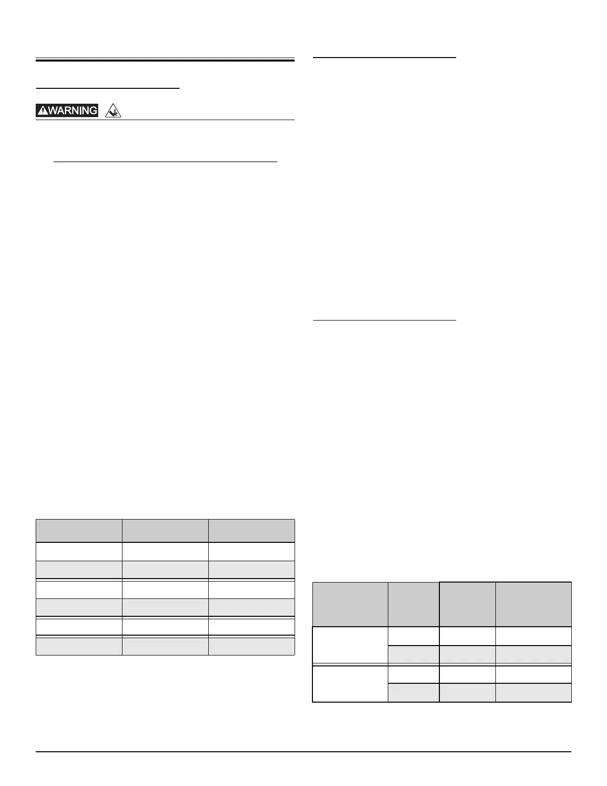
1-phase pumps require a panel-moun
ted run capacitor. Refer to
Table 1.
Model Run Capacitor Capacitor Kit
Thermostats
XFL-Series pumps are protected from overheating by thermal
switches (thermostats) located in the motor. For 1-phase models,
a hermetically sealed thermostat is mounted on the motor
windings and wired directly in series with the motor’s winding,
interrupting power in a high heat condition. 3-phase models
utilize two thermostats mounted in series directly on the motor
windings, thus monitoring the pump’s internal temperatures. The
thermostat circuit must be connected in such a way as to open the
motor contactors in the panel cutting power to the pump in an
overheat condition.
Both 1-phase and 3-phase pumps a
re designed to operate under
class B insulation with a heat rise of 266°F (130°C) internal
temperatures, even though the motors are constructed with class
F materials. Failure to use the proper circuitry and connection of
the thermostat will drop T class to T3 on 3-phase models.
Many control panels have a manu
al reset button for the
thermostats on 3-phase models. This button must be pressed to
reset the system after the pump has cooled. 1-phase models
automatically reset after the pump has cooled to a safe
temperature.
Seal Failure Probes
XFL-Series pumps are equipped with two mechanical face seals
with an oil chamber between them to provide permanent
lubrication to the seals. A seal fail or moisture sensing device is
located in the mid oil chamber and continuously monitors for
leakage. Should moisture mix with the oil, an indicator light will
illuminate on the control panel indicating a shaft seal failure has
occurred and the pump is in need of service. The pump will
continue to operate as normal but service should be scheduled as
soon as possible.
Intrinsically safe (ISS and ISD Series) pa
nels by Liberty Pumps have
a seal leak test button that tests the integrity of the seal leak
circuit continuity. When pressed, the light should illuminate. If it
does not, either the light is burned out, the circuitry is open, or the
system does not have power.
The seal leak module is located
inside the panel and requires
adjustment upon installation. See Seal leak relay setup on
page 7.
Seal fail probes connect to a relay in the control panel, which is
included in a Liberty Pumps control panel. For a non-Liberty
Pumps control panel or for a replacement relay, refer to Table 2.
Description
Relay
Input
Voltage
Liberty
Pumps
P/N
Macromatic
P/N
RISK OF SERIOUS INJURY OR DEATH
Table 1. Capacitor Kits
XFL51 50 µF 370 VAC K001515
XFL52 45 µF 370 VAC K001514
XFL71 50 µF 370 VAC K001515
XFL72 45 µF 370 VAC K001514
XFL102 40 µF 370 VAC K001585
XFL152 40 µF 370 VAC K001585
Table 2. Seal Fail Replacement Relay
Simplex, controls
1 pump
120V K001672 SFP120A250
240V K001673 SFP240A250
Duplex, controls
2 pumps
120V K001675 SFP120C250
240V K001676 SFP240C250
Bekijk gratis de handleiding van Liberty Pumps XFL150, stel vragen en lees de antwoorden op veelvoorkomende problemen, of gebruik onze assistent om sneller informatie in de handleiding te vinden of uitleg te krijgen over specifieke functies.
Productinformatie
| Merk | Liberty Pumps |
| Model | XFL150 |
| Categorie | Niet gecategoriseerd |
| Taal | Nederlands |
| Grootte | 2016 MB |


