Handleiding
Je bekijkt pagina 73 van 84
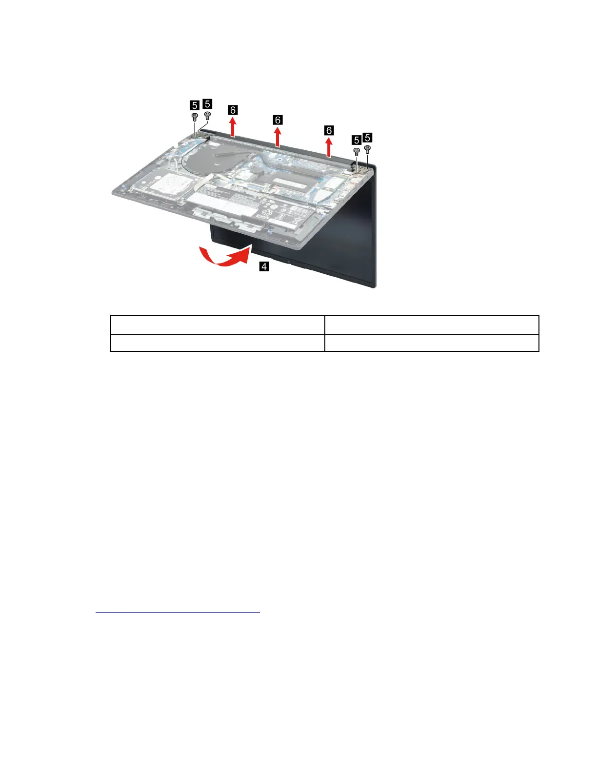
Step 3. Rotate the LCD unit to an angle of more than 90 degrees and place the computer on a flat surface
as shown. Remove four screws and then remove the LCD module.
Figure 66. Remove four screws and then remove the LCD module
Screw specifications Number of screws
M2.5 x L5 4
Remove the upper case
Make sure the following FRUs (CRUs) have been removed.
“Remove the lower case” on page 54
“Remove the hard disk drive (HDD) module” on page 55
“Remove the battery pack” on page 56
“Remove the solid-state drive (SSD) module” on page 57
“Remove the Wi-Fi card” on page 58
“Remove the CMOS battery” on page 59
“Remove the memory module” on page 60
“Remove the heat sink” on page 61
“Remove the fan” on page 61
“Remove the I/O board module” on page 62
“Remove the system board and the touchpad board cable” on page 64
“Remove the LCD module” on page 66
Go to
https://support.lenovo.com/partslookup to look up the Lenovo part number of the following replacement
part:
Upper case
Disassemble the LCD module
The LCD module as a whole is not an FRU. Instead, it contains FRUs as its components. Before
disassembling the LCD module, make sure it has been detached from the upper case.
Chapter 4. Removing a FRU or CRU 67
Bekijk gratis de handleiding van Lenovo V15 Gen 3, stel vragen en lees de antwoorden op veelvoorkomende problemen, of gebruik onze assistent om sneller informatie in de handleiding te vinden of uitleg te krijgen over specifieke functies.
Productinformatie
| Merk | Lenovo |
| Model | V15 Gen 3 |
| Categorie | Laptop |
| Taal | Nederlands |
| Grootte | 20888 MB |


