Lectrosonics SMWB/E01 handleiding
Handleiding
Je bekijkt pagina 17 van 30
Digital Hybrid Wireless Belt-Pack Transmitters
Rio Rancho, NM 17
Microphone RF Bypassing
When used on a wireless transmitter, the microphone
element is in the proximity of the RF coming from the
transmitter. The nature of electret microphones makes
them sensitive to RF, which can cause problems with
microphone/transmitter compatibility. If the electret mi-
crophone is not designed properly for use with wireless
transmitters, it may be necessary to install a chip capaci-
tor in the mic capsule or connector to block the RF from
entering the electret capsule.
Some mics require RF protection to keep the radio signal
from aecting the capsule, even though the transmitter
input circuitry is already RF bypassed.
If the mic is wired as directed, and you are having dif-
culty with squealing, high noise, or poor frequency
response, RF is likely to be the cause.
The best RF protection is accomplished by installing RF
bypass capacitors at the mic capsule. If this is not pos-
sible, or if you are still having problems, capacitors can
be installed on the mic pins inside the TA5F connector
housing. Refer to the diagram below for the correct loca-
tions of capacitors.
Use 330 pF capacitors. Capacitors are available from
Lectrosonics. Please specify the part number for the
desired lead style.
Leaded capacitors: P/N 15117
Leadless capacitors: P/N SCC330P
All Lectrosonics lavaliere mics are already bypassed and
do not need any additional capacitors installed for proper
operation.
CAPSULE
CAPSULE
SHIELD
AUDIO
SHIELD
AUDIO
BIAS
TA5F
CONNECTOR
TA5F
CONNECT
OR
2-WIRE MIC 3-WIRE MIC
Capacitors next
to mic capsule
Capacitors in
TA5F connector
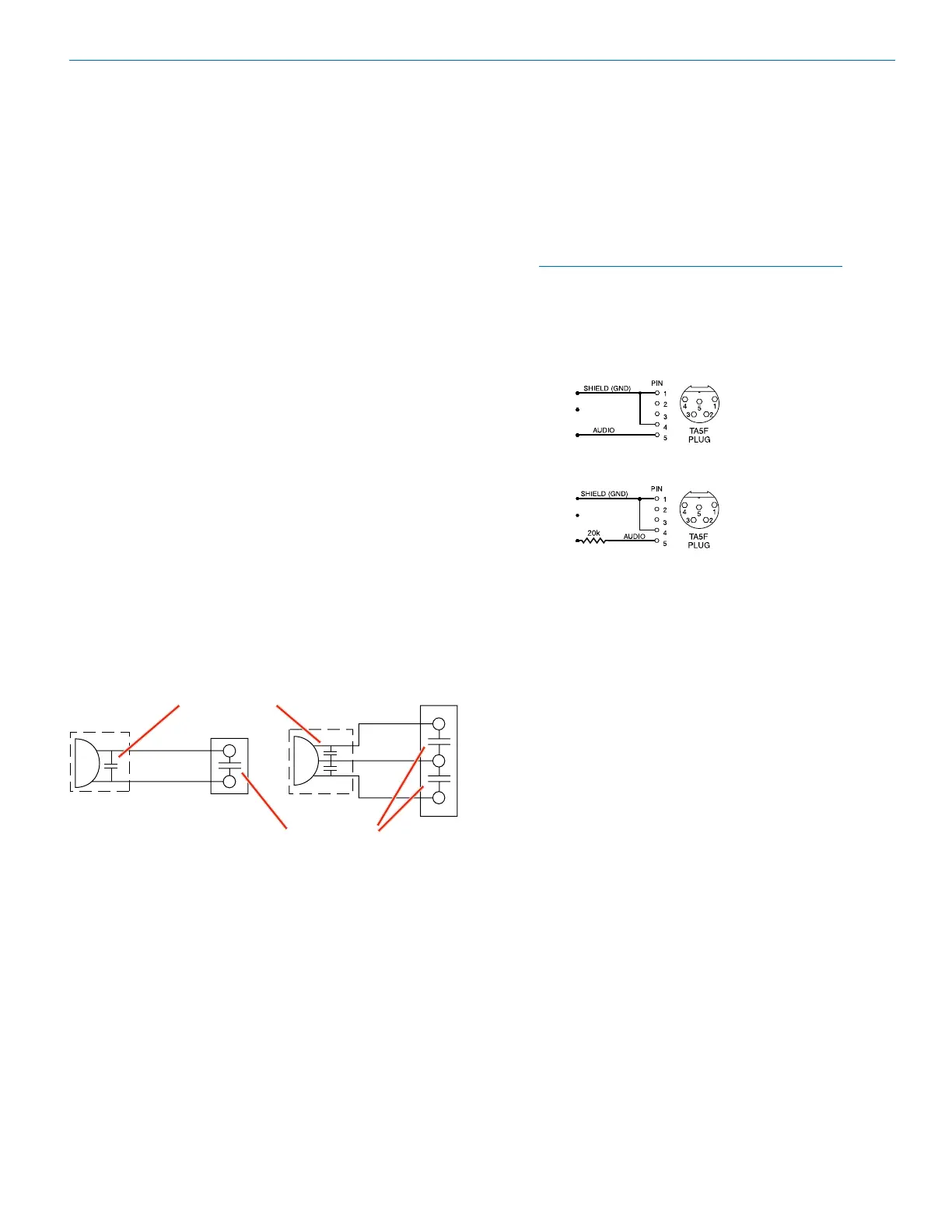
Line Level Signals
The wiring for line level and instrument signals is:
• Signal Hot to pin 5
• Signal Gnd to pin 1
• Pin 4 jumped to pin 1
This allows signal levels up to 3V RMS to be applied
without limiting.
NOTE for line level inputs only (not instrument):
If more headroom is needed, insert a 20 k
resistor in series with pin 5. Put this resistor
inside the TA5F connector to minimize noise
pickup. The resistor will have little or no effect
on the signal if the input is set for instrument.
See Fig. 8 on
previous page
Line Level
Normal Wiring
Line Level
More Headroom
(20 dB)
Bekijk gratis de handleiding van Lectrosonics SMWB/E01, stel vragen en lees de antwoorden op veelvoorkomende problemen, of gebruik onze assistent om sneller informatie in de handleiding te vinden of uitleg te krijgen over specifieke functies.
Productinformatie
| Merk | Lectrosonics |
| Model | SMWB/E01 |
| Categorie | Niet gecategoriseerd |
| Taal | Nederlands |
| Grootte | 7735 MB |


