Laserliner VideoInspector 3D Micro handleiding
Handleiding
Je bekijkt pagina 8 van 92
1
2
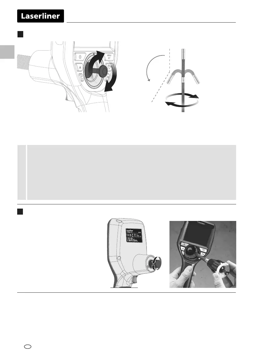
The camera unit is easy to remove and
replace. Simply undo the screw and
pull out the camera unit by
the joystick.
08
Information on maintenance and care
Clean all components with a damp cloth and do not use cleaning agents, scouring agents and solvents.
Store the device in a clean and dry place.
3
Replacement of the camera unit
2
Camera head adjustment
The factory setting for the maximum angular position of the 3D camera head is 150° in new condition,
with a tolerance of ± 10°. To achieve this, the camera probe must be totally straight, meaning without any
unnecessary curves or bends. The maximum angular position may be reduced by normal mechanical wear
over the lifetime of the product.
The movable 3D camera head must not be subjected to heavy mechanical loads when in an
angled position. Observe the maximum angular position, minimum bending radius and maximum
traction force to prevent damage to the 3D camera head. Do not snatch or push the camera probe
with a jerky movement. The camera head must never be moved by hand when in use; always use
the control lever instead. When rolled up, the camera probe must not be moved either by hand or
by the control lever.
This warranty does not cover damage to the 3D camera head or probe
caused by incorrect handling.
!
EN
0°
360°
150°
±10°
Bekijk gratis de handleiding van Laserliner VideoInspector 3D Micro, stel vragen en lees de antwoorden op veelvoorkomende problemen, of gebruik onze assistent om sneller informatie in de handleiding te vinden of uitleg te krijgen over specifieke functies.
Productinformatie
| Merk | Laserliner |
| Model | VideoInspector 3D Micro |
| Categorie | Niet gecategoriseerd |
| Taal | Nederlands |
| Grootte | 9596 MB |


