KStrong UFA20006 handleiding
Handleiding
Je bekijkt pagina 7 van 13
06
If the only available anchorage is situated below the attachment on the harness; and if there is a risk of fall, then it
is essential to use a lanyard with a properly rated energy absorber. It is important to ensure that there is sufficient
fall clearance below the user, before using a shock absorbing lanyard. If the weight of a wearer is 220 lbs. and the
fall factor is two, we can calculate the fall clearance (which will be equal to the stopping distance H (2L+ 5.74 ft.) +
an additional distance of 3.28 ft.
PERIODIC EXAMINATION
IF USED NEAR CORROSIVE ENVIRONMENT
Ÿ Swing Falls: Swing falls occurs when the position of the anchorage point is not directly above the point where a
fall occurs. In such a case if a fall were to occur, it will result in pendulum swing of the fall victim and may also
cause them to strike nearby objects with a force. This may cause serious injury or even death. Such swing falls
may be minimized by ensuring that the anchorage is directly overhead, and by working as close to the anchorage
point as possible. Swing falls will substantially increase the fall clearance required when a SRL or other variable
length connecting subsystems are used.
In corrosive environments or in areas near the seawater, metallic connectors, hooks and anchorages have a greater
chance of corrosion and rusting. Hence, the frequency of their inspection must be altered so as to check their
functioning and performance more frequently.
When connecting an energy absorbing lanyard to the dorsal attachment D-ring of the harness, connect only the
shock-pack end of the lanyard to the D-ring. The other end of the lanyard is connected to the anchorage point.
A lifeline should never be connected to a connector using a knot. Also, never tie-back a connector on to a lifeline or the
lanyard. Use a spliced end termination and a thimble to attach a connector to a synthetic rope lifeline. Connectors which
are required to attach to wire rope lifelines must be attached to a thimble on a formed eye termination of the wire rope. It
is important to ensure that the termination is secured properly by swaging the ends of the wire rope by following proper
procedures, before the thimble is connected to a connector.
IMPORTANT POINTS FOR SUBSYSTEM ASSEMBLIES
While making connections, ensure that all connectors are fully closed and locked.
The user must always keep the instructions provided with the product. Take the information from the markings on the
product and enter this information in the identification sheet. To ensure the safety of the user, it is essential to check the
condition of the equipment through periodic examinations of the product. This equipment must be examined by a
qualified person at least once every six months, strictly complying with the manufacturer's instructions. Also, record the
previous check on the attached sheet. If the equipment is in heavy usage or is used in a harsh environment, then the
frequency of inspection should be increased in accordance with the regulations. Check also that the markings on the
product are legible.
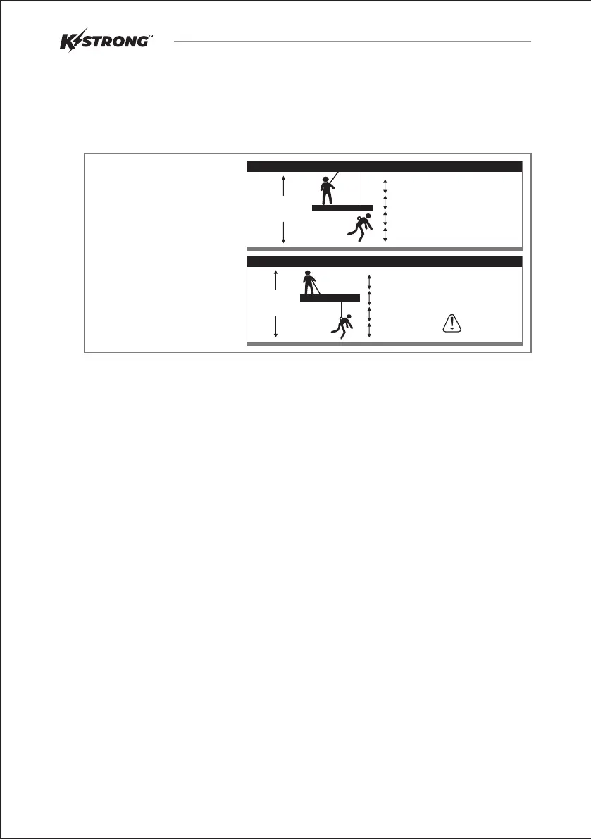
Free Fall Distance + Energy Absorber
Deceleration Distance + Worker height +
Safety Factor = 19 ft. (5.8 m)
Free Fall Distance + Energy Absorber
Deceleration Distance + Worker height +
Safety Factor = 20 ft. (6.1 m)
Total Fall Clearance below worker is
calculated from Anchorage Connection.
Free Fall Distance + Energy Absorber
Deceleration Distance + Worker height +
Safety Factor. Care must be taken to
ensure that the total fall distance is clear
of obstructions; such as equipment, to
avoid contact with a lower level.
Calculating Total Fall Distances:
This Application
requires a special
EA lanyard
Total 19 ft.
from Anchorage
6 ft. free Fall
Before
After
3 ft. Safety Factor
6 ft. Length of Energy Absorbing Lanyard
4 ft. Deceleration Distance
6 ft. Height of Worker
Anchorage
12 ft. Free Fall
Total 20 ft.
from Anchorage
Before
After
Anchorage
3 ft. Safety Factor
6 ft. Length of Energy Absorbing Lanyard
5 ft. Deceleration Distance
6 ft. Height of Worker
Bekijk gratis de handleiding van KStrong UFA20006, stel vragen en lees de antwoorden op veelvoorkomende problemen, of gebruik onze assistent om sneller informatie in de handleiding te vinden of uitleg te krijgen over specifieke functies.
Productinformatie
| Merk | KStrong |
| Model | UFA20006 |
| Categorie | Niet gecategoriseerd |
| Taal | Nederlands |
| Grootte | 1499 MB |


