JET JWJ-8HH-BLK handleiding
Handleiding
Je bekijkt pagina 16 van 28
16
Figure 9-9
9.5 Replacing or Rotating Knife
Inserts
Refer to Figure 9-10:
The knife inserts are four-sided. When dull, simply
remove each insert, rotate it 90° for a fresh edge,
and re-install it.
Use the two provided star point screwdrivers to
remove the knife insert screw (see Figure 9-10). Use
one of the screwdrivers to help hold the cutterhead
in position, and the other to remove the screw. It is
advisable to rotate all inserts at the same time to
maintain consistent cutting. However, if one or more
knife inserts develops a nick, rotate only those
inserts that are affected.
Each knife insert has an etched reference mark so
that you can keep track of the rotations.
IMPORTANT: When removing or rotating inserts,
clean saw dust from the screw, the insert, and the
cutterhead platform. Dust accumulation between
these elements can prevent the insert from seating
properly and may affect the quality of the cut.
Before installing each screw, lightly coat the screw
threads with machine oil and wipe off any excess.
Securely tighten each screw which holds the knife
inserts before operating the planer!
Make sure all knife insert
screws are tightened securely. Loose inserts
can be propelled at high speed from a rotating
cutterhead, causing injury.
Figure 9-10
9.6 Infeed Table Depth Stop
Refer to Figure 9-11:
The infeed table travel limiter located on the back of
the table sets the upper and lower range for the
infeed table height adjustment and should not
require any adjustments.
The infeed table depth stop (A) limits the depth of a
cut (set by adjusting the infeed table handwheel) to
a maximum depth of 1/8”. For normal operations, a
depth of cut of 1/8" or less is recommended.
Figure 9-11
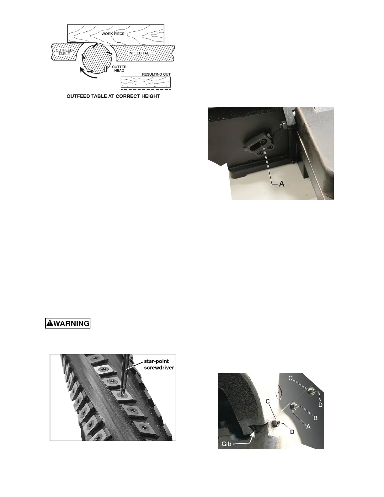
9.7 Gib Adjustment
Refer to Figure 9-12:
The gibs are located on both the infeed and outfeed
tables. After a period of use, the gibs may become
loose and need adjusting:
1. The center lock nut (A) and set screw (B) are
very tight in order to lock the outfeed table in
position. Before adjusting the gib, loosen the
center lock nut first, and then loosen the center
set screw.
2. Loosen two lock nuts (C) at the bottom and top
of the table seat.
3. Tighten the bottom and top set screws (D) 1/4
turn. If a 1/4 turn does not remove all play, take
another 1/4 turn. Repeat a 1/4 turn for both set
screws until play is removed.
4. Tighten two lock nuts (C) at the bottom and top
of the table seat.
5. Firmly tighten the center set screw (B) first,
and then tighten the center lock nut (A).
Figure 9-12
Bekijk gratis de handleiding van JET JWJ-8HH-BLK, stel vragen en lees de antwoorden op veelvoorkomende problemen, of gebruik onze assistent om sneller informatie in de handleiding te vinden of uitleg te krijgen over specifieke functies.
Productinformatie
| Merk | JET |
| Model | JWJ-8HH-BLK |
| Categorie | Niet gecategoriseerd |
| Taal | Nederlands |
| Grootte | 9382 MB |


