Handleiding
Je bekijkt pagina 8 van 24
8
EN
CEILING CUTOUT SIZES
Packaged with the speakers are cardboard cutout templates for scribing the cutout hole onto your ceiling surface.
Table 2: Cutout Sizes
Model Cutout Size (diameter)
Control 424C/T 168 mm (6.6 in)
Control 424LP, 426C/T & 426LP, 426C/T-LS 223 mm (8.8 in)
Control 419CS/T 305 mm (12.2 in)
OPTIONAL BG (black) and SG (square) GRILLES
Optional round black and white square magnetic grilles are available. The JBL-MTC-xxxBG grilles are round Black Grilles that
can be utilized instead of the included stock white grille for when black is called for. Alternatively, the stock white grille can be
painted (see below). The JBL-MTC-xxxSG are white Square Grilles that can be utilized instead of the included stock grille for
when a square grille is desired. These grilles can be painted to the desired color (including black). These grilles completely cover
the speaker assembly.
For Control 426C/T-LS, the accessory grilles are JBL-MTC-426BG-LS and JBL-MTC-426SG-LS, and in order to maintain the
ammability rating required by the UL1480 life safety rating, they are NOT paintable.
STEP-BY-STEP
INSTALLATION AND WIRING
The installation system has been designed so that the entire installation can be accomplished from beneath the ceiling for
instances when access above the tile is not possible or practical. However, in some cases it may be easier -- with removable
ceiling tiles, for example -- to access from both the top and bottom of the ceiling tile during various phases of the installation.
Note 1: the wiring method shall be in accordance with:
(1) In Canada, CSA C22.1, Canadian Electrical Code, Part I, Safety Standard for Electrical Installations, Section 32
(2) In the United States, NFPA 70 and NFPA 72.
Note 2: this product is not suitable for use in connection with rigid conduit.
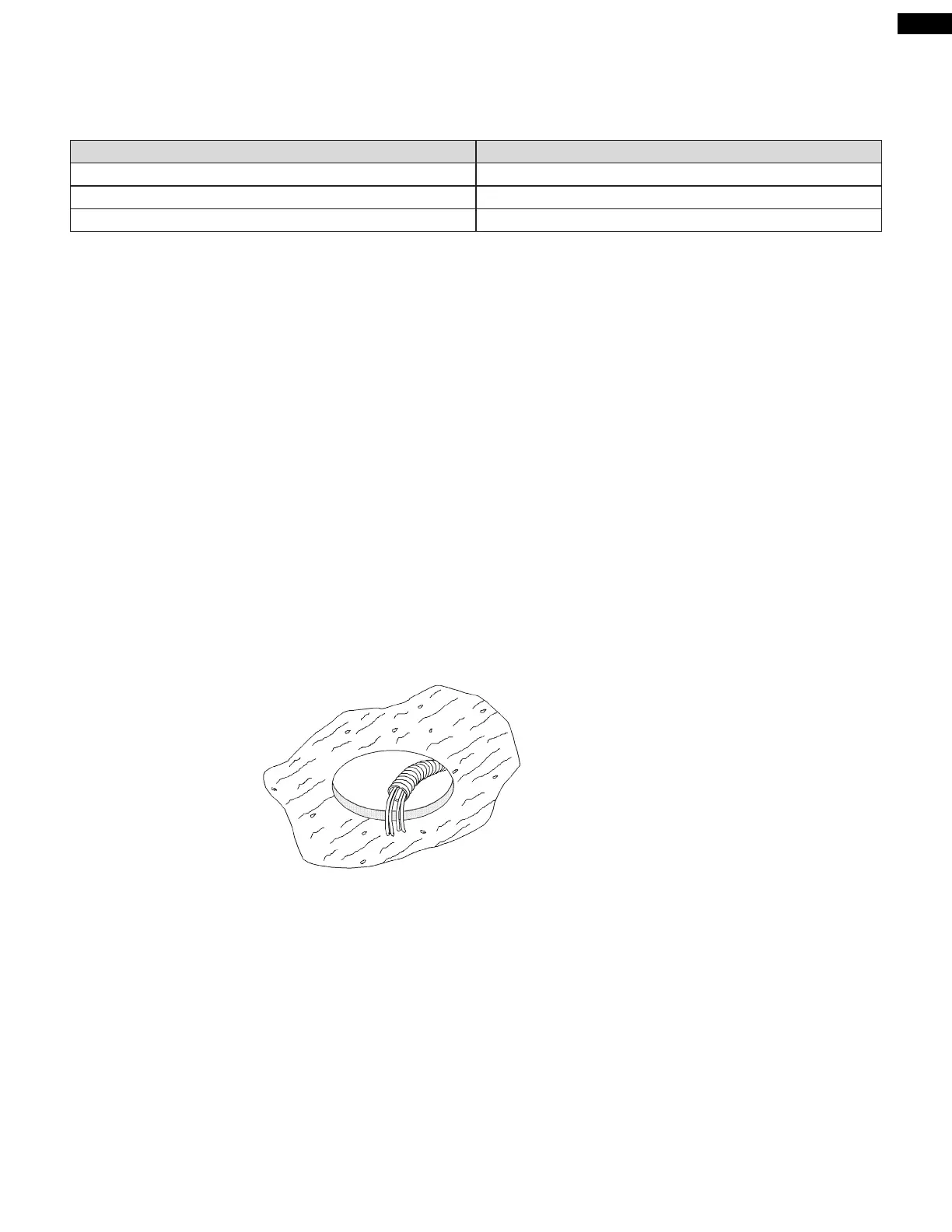
Step 1 – Cut the Hole. Cutout the hole size either by tracing the included cardboard cutout template or by scribing a hole using
the cutout size chart above. Use a safe tool such as a jigsaw to cut the hole and proper eye protection. Be precise, not deviating
from the cutout diameter by more than 1/16th of an inch (1.5 mm). Pull the wiring through the cutout hole.
Figure 3:
Hole Cutout
(Shown: Wire in ex conduit)
Step 2 – Insert Backing Hardware Through the Hole. Packaged with the speakers are two types of backing hardware – a
C-shaped backing-plate (“C-ring”) bracket and two tile rails.
Suspended Ceilings – Insert the C-ring through the hole cut in the ceiling tile (or set it in place from above the ceiling, if there is
access). Place the C-ring around the hole with the tabs located as shown on Figure 4. Insert the tile rails through the cut hole in
the ceiling tile. Snap the two rails into the two tabs in the C-plate and align the rails so that the ends extend OVER the T-channel
grid on the side of the tile. Secure the rails onto the C-ring tabs by inserting a screw though each tab into the rail. This can all be
accomplished from below the ceiling tile, if necessary.
FOR SAFETY: IMPORTANT TO USE BRACKETS
ALL included support brackets – C-ring and tile rails -- MUST be used when installing into suspended ceiling tiles.
Bekijk gratis de handleiding van JBL Control 424LP, stel vragen en lees de antwoorden op veelvoorkomende problemen, of gebruik onze assistent om sneller informatie in de handleiding te vinden of uitleg te krijgen over specifieke functies.
Productinformatie
| Merk | JBL |
| Model | Control 424LP |
| Categorie | Speaker |
| Taal | Nederlands |
| Grootte | 3321 MB |


