Janitza 800-DI14 handleiding
Handleiding
Je bekijkt pagina 22 van 44
22
800-DI14 module
www.janitza.com
1
3
4
2
5
6
6
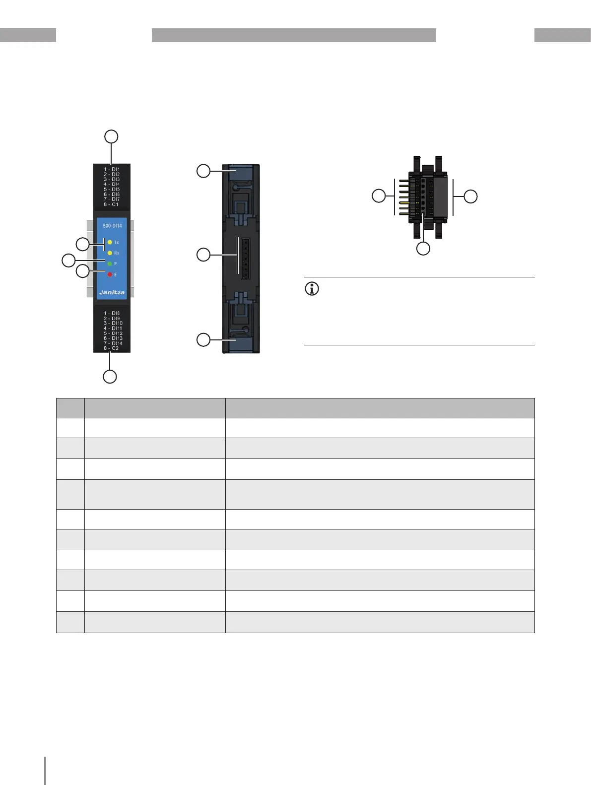
Item Designation Description
1 Connections, 8-pin Digital inputs (bottom of module).
2 LED (E ... Error)
Lights "red" during initialization/startup and in the event of a fault (error).
Take note in this regard of Sect. “15.2 Modules - Error cases” on p. 39.
3 LED (P ...Power)
Lights "green" if the supply of power via the JanBus
interface of the basic device is correct; the device is ready for operation.
4
2 LEDs
(Tx... Transmit data, Rx... Receive
data)
Blink "orange" during operation and indicate cyclic data exchange.
5 Connections, 8-pin Digital inputs (top of module).
6 Bottom bolts For mounting the module on the DIN rail.
7
JanBus interface -
rear of module
Connection contacts for the communication bus connector (item 8).
8
Communication bus connector -
JanBus interface
Bus connector insert (sockets) into the module
9
Communication bus connector -
JanBus interface
Connection to a basic device (or connected modules).
10
Communication bus connector -
Bus connector contacts (JanBus)
Connection of additional modules.
7
9
8
10
INFORMATION
The digital input module is supplied with the neces-
sary screw terminals and bus connectors (JanBus
interface) for connection to a basic device or other
modules.
5. Connections/controls
Bekijk gratis de handleiding van Janitza 800-DI14, stel vragen en lees de antwoorden op veelvoorkomende problemen, of gebruik onze assistent om sneller informatie in de handleiding te vinden of uitleg te krijgen over specifieke functies.
Productinformatie
| Merk | Janitza |
| Model | 800-DI14 |
| Categorie | Niet gecategoriseerd |
| Taal | Nederlands |
| Grootte | 5503 MB |


