Janitza 800-CT24 handleiding
Handleiding
Je bekijkt pagina 44 van 60
800-CT24 module www.janitza.com
44
ESC
Home
Phasor diagram
Voltage
Current
Power
Menu
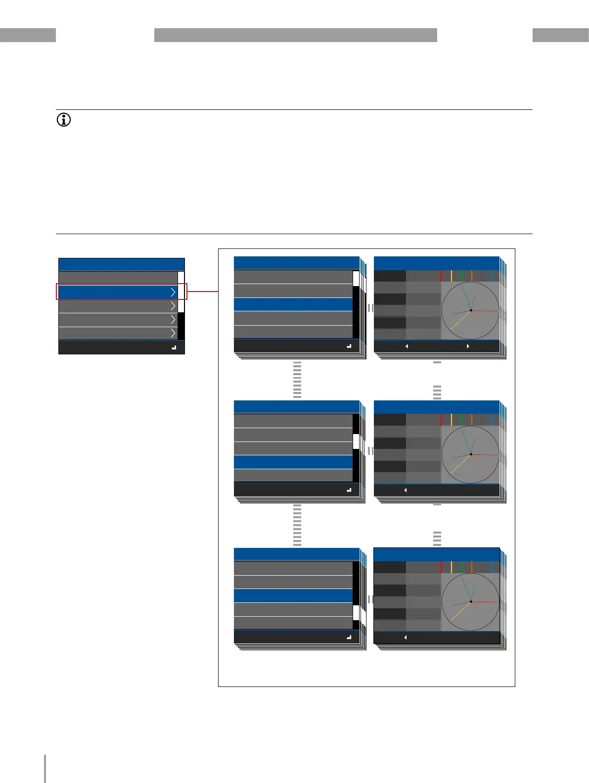
11. Module-relevant measuring displays of the basic device with 3
modules of the type 800-CT24
L5 229.8V
2.227A44.0°
41.0 °
50.0°
2.229A
2.229A
230.0V
U1 U2 U3 I5 I6 I7
L6
L7
ESC
229.7V
2. 800-CT24 5-8
L5 229.8V
2.227A44.0°
41.0 °
50.0°
2.229A
2.229A
230.0V
U1 U2 U3 I5 I6 I7
L6
L7
ESC
229.7V
2. 800-CT24 5-8
L5 229.8V
2.227A44.0°
41.0 °
50.0°
2.229A
2.229A
230.0V
U1 U2 U3 I5 I6 I7
L6
L7
ESC
229.7V
2. 800-CT24 5-8
L5 229.8V
2.227A44.0°
41.0 °
50.0°
2.229A
2.229A
230.0V
U1 U2 U3 I5 I6 I7
L6
L7
ESC
229.7V
2. 800-CT24 5-8
L5 229.8V
2.227A44.0°
41.0 °
50.0°
2.229A
2.229A
230.0V
U1 U2 U3 I5 I6 I7
L6
L7
ESC
229.7V
2. 800-CT24 5-8
L5 229.8V
2.227A44.0°
41.0 °
50.0°
2.229A
2.229A
230.0V
U1 U2 U3 I5 I6 I7
L6
L7
ESC
229.7V
2. 800-CT24 5-8
L5 229.8V
2.227A44.0°
41.0 °
50.0°
2.229A
2.229A
230.0V
U1 U2 U3 I5 I6 I7
L6
L7
ESC
229.7V
2. 800-CT24 5-8
L5 229.8V
2.227A44.0°
41.0 °
50.0°
2.229A
2.229A
230.0V
U1 U2 U3 I5 I6 I7
L6
L7
ESC
229.7V
2. 800-CT24 5-8
L5 229.8V
2.227A44.0°
41.0 °
50.0°
2.229A
2.229A
230.0V
U1 U2 U3 I5 I6 I7
L6
L7
ESC
229.7V
2. 800-CT24 5-8
L5 229.8V
2.227A44.0°
41.0 °
50.0°
2.229A
2.229A
230.0V
U1 U2 U3 I5 I6 I7
L6
L7
ESC
229.7V
2. 800-CT24 5-8
L1 230.0V
2.229A45.0°
40.0°
52.0°
2.228A
2.228A
229.7V
U1 U2 U3 I1 I2 I3
L2
L3
ESC
229.7V
Zeigerdiagramm 3. 800-CT8-A 1-4
L1 230.0V
2.229A45.0°
40.0°
52.0°
2.228A
2.228A
229.7V
U1 U2 U3 I1 I2 I3
L2
L3
ESC
229.7V
Zeigerdiagramm 3. 800-CT8-A 1-4
L1 230.0V
2.229A45.0°
40.0°
52.0°
2.228A
2.228A
229.7V
U1 U2 U3 I1 I2 I3
L2
L3
ESC
229.7V
Zeigerdiagramm 3. 800-CT8-A 1-4
L1 230.0V
2.229A45.0°
40.0°
52.0°
2.228A
2.228A
229.7V
U1 U2 U3 I1 I2 I3
L2
L3
ESC
229.7V
Zeigerdiagramm 3. 800-CT8-A 1-4
L1 230.0V
2.229A45.0°
40.0°
52.0°
2.228A
2.228A
229.7V
U1 U2 U3 I1 I2 I3
L2
L3
ESC
229.7V
Zeigerdiagramm 3. 800-CT8-A 1-4
2. 800-CT24 17-20
2.
800-CT24 21-24
3. 800-CT24 1-4
3.
800-CT24 5-8
3.
800-CT24 9 -12
ESC
Phasor diagram
1. 800-CT24 21-24
1.
800-CT24 17-20
2.
800-CT24 1-4
2.
800-CT24 5-8
2. 800-CT24 9 -12
ESC
Phasor diagram
1. 800-CT24 21-24
1.
800-CT24 17-20
2.
800-CT24 1-4
2.
800-CT24 5-8
2.
800-CT24 9 -12
ESC
Phasor diagram
1. 800-CT24 21-24
1.
800-CT24 17-20
2.
800-CT24 1-4
2.
800-CT24 5-8
2.
800-CT24 9 -12
ESC
Phasor diagram
1. 800-CT24 21-24
1.
800-CT24 17-20
2.
800-CT24 1-4
2.
800-CT24 5-8
2.
800-CT24 9 -12
ESC
Phasor diagram
1. 800-CT24 21-24
1.
800-CT24 17-20
2.
800-CT24 1-4
2.
800-CT24 5-8
2.
800-CT24 9 -12
ESC
Phasor diagram
Basic device 5-8
Basic device 1-4
Phasor diagram
ESC
1. 800-CT24 5-8
1.
800-CT24 9 -12
1.
800-CT24 1-4
Basic device 5-8
Basic device 1-4
Phasor diagram
ESC
1. 800-CT24 5-8
1.
800-CT24 9 -12
1.
800-CT24 1-4
Basic device 5-8
Basic device 1-4
Phasor diagram
ESC
1. 800-CT24 5-8
1.
800-CT24 9 -12
1.
800-CT24 1-4
Basic device 5-8
Basic device 1-4
Phasor diagram
ESC
1. 800-CT24 5-8
1.
800-CT24 9 -12
1.
800-CT24 1-4
1. 800-CT24 21-24
1.
800-CT24 17-20
2.
800-CT24 1-4
2.
800-CT24 5-8
2. 800-CT24 9 -12
ESC
Phasor diagram
L1 230.0V
2.229A45.0°
40.0°
52.0°
2.228A
2.228A
229.7V
U1 U2 U3 I1 I2 I3
L2
L3
ESC
229.7V
1. 800-CT24 1-4
L5 229.8V
2.227A44.0°
41.0 °
50.0°
2.229A
2.229A
230.0V
U1 U2 U3 I5 I6 I7
L6
L7
ESC
229.7V
2. 800-CT24 5-8
Menu (phasor diagram)
1. Module 800-CT24 - measurement channels
1-4: Display, Voltage L1, L2, L3; current L1, L2, L3;
phase shift between voltage and current L1, L2, L3.
L5 229.8V
2.227A44.0°
41.0 °
50.0°
2.229A
2.229A
230.0V
U1 U2 U3 I5 I6 I7
L6
L7
ESC
229.7V
3. 800-CT24 1-4
Basic device 5-8
Basic device 1-4
Phasor diagram
ESC
1. 800-CT24 5-8
1.
800-CT24 9 -12
1.
800-CT24 1-4
Basic device 5-8
Basic device 1-4
Phasor diagram
ESC
1. 800-CT24 5-8
1.
800-CT24 9 -12
1.
800-CT24 1-4
2. 800-CT24 17-20
2.
800-CT24 21-24
3. 800-CT24 1-4
3.
800-CT24 5-8
3. 800-CT24 9 -12
ESC
Phasor diagram
2. 800-CT24 17-20
2.
800-CT24 21-24
3. 800-CT24 1-4
3.
800-CT24 5-8
3. 800-CT24 9 -12
ESC
Phasor diagram
2. 800-CT24 17-20
2.
800-CT24 21-24
3. 800-CT24 1-4
3. 800-CT24 5-8
3.
800-CT24 9 -12
ESC
Phasor diagram
2. 800-CT24 17-20
2.
800-CT24 21-24
3. 800-CT24 1-4
3.
800-CT24 5-8
3.
800-CT24 9 -12
ESC
Phasor diagram
2. 800-CT24 17-20
2.
800-CT24 21-24
3. 800-CT24 1-4
3.
800-CT24 5-8
3. 800-CT24 9 -12
ESC
Phasor diagram
2. Module 800-CT24 - measurement channels
5-8: Display, Voltage L1, L2, L3; current L1, L2, L3;
phase shift between voltage and current L1, L2, L3.
3. Module 800-CT24 - measurement channels
1-4: Display, Voltage L1, L2, L3; current L1, L2, L3;
phase shift between voltage and current L1, L2, L3.
INFORMATION
· The following measured value and device displays of the basic device refer to the measurement de-
vice and module topology described in Sect. 9.2 on page 36.
· The displays may vary depending on the type of basic device and the measuring environment!
· You can change the names of the basic device, the modules or the measurement groups shown in the mea-
surement device display using the device configuration of the GridVis
®
software.
· The measurement device display shows the measurement group names with the respective position num-
ber of the module.
· Depending on the text length, measurement group names appear as scrolling text in the title line of the
measurement device display.
· Further measured value and device displays can be found in the usage information for the basic device.
Bekijk gratis de handleiding van Janitza 800-CT24, stel vragen en lees de antwoorden op veelvoorkomende problemen, of gebruik onze assistent om sneller informatie in de handleiding te vinden of uitleg te krijgen over specifieke functies.
Productinformatie
| Merk | Janitza |
| Model | 800-CT24 |
| Categorie | Niet gecategoriseerd |
| Taal | Nederlands |
| Grootte | 9037 MB |


