Ixxat CAN@net II/VCI handleiding
Handleiding
Je bekijkt pagina 9 van 22
CAN@net II - Manual, V2.0
Connections and Indicators
9
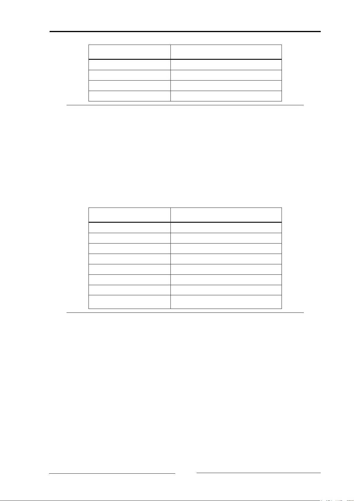
Pin No.
Signal
1
V+ (+9 V to +32 V DC)
2
V-
3
Output 1 (optional)
4
Output 2 (optional)
Table 3-1: Pin allocation of the power connector
The power connector is just plugged into the housing and can be removed with
a screwdriver or similar tool.
3.1.2 Ethernet Socket
The Ethernet socket is designed as a standard RJ45 socket. The pin allocation
is according to the Ethernet standard. The Ethernet PHY has an auto-crossover
feature, so the CAN@net II can be connected with a crossover cable or with a
1-to-1 network cable.
Pin No. RJ45
Signal
1
TX +
2
TX -
3
RX +
4
Connected to pin 5
5
Connected to pin 4
6
RX -
7
Connected to pin 8
8 Connected to pin 7
Table 3-2: Pin allocation of the Ethernet socket
The shield of the socket is connected to the ground of the printed board via a
1 nF capacitor.
Bekijk gratis de handleiding van Ixxat CAN@net II/VCI, stel vragen en lees de antwoorden op veelvoorkomende problemen, of gebruik onze assistent om sneller informatie in de handleiding te vinden of uitleg te krijgen over specifieke functies.
Productinformatie
| Merk | Ixxat |
| Model | CAN@net II/VCI |
| Categorie | Niet gecategoriseerd |
| Taal | Nederlands |
| Grootte | 4008 MB |
