Intermatic ET90115M handleiding
Handleiding
Je bekijkt pagina 6 van 48
ET90000 Series Electronic Timer
6
INSTALL WIRING
Observe these regulations before connecting any
applications to the device.
• The circuit conductors shall have an ampacity
not less than the maximum total load to be
controlled.
• Over current protection shall have an interrupting
rating sufficient for the application control circuit
voltage and the total load current of the equipment
being controlled.
• A fuse or circuit breaker shall be connected in
series with each ungrounded conductor (and shall
be able to open each conductor simultaneously).
• Maximum current rating for each circuit is 30 amps
Resistive and General Purpose. Refer to the Power
Ratings section on page 3 for other ratings.
Wire components and applications to the terminal boards
as needed. Terminal boards are located underneath
the faceplate on the small unit, and on the right and left
sides of the large unit. Insert wires into slots; secure with
athead screwdriver.
WIRING INFORMATION – COPPER CONDUCTORS ONLY
WIRE SIZE
105°C MIN
INSULATION
SUPPLY
CIRCUIT
BREAKER
RATING
MAX MOTOR LOAD
(CONTINUOUS DUTY)
120 V 240 V
AWG AMP HP HP
14 15 1/2 1
12 20 1 2
10 30 – –
Terminal block wire gauge range 20 to 6 AWG
ADDING RELAY BOARDS (4, 8, 12 CIRCUIT
SYSTEMS)
You can add additional four-circuit relay boards to the 4,
8 and 12 circuit model to a maximum of 16 circuits per
system.
IMPORTANT: Do not exceed 350 amps maximum panel
load.
1. Open outer door and remove and retain the two
screws that secure the interior deadfront to the
chassis.
2. Remove and retain the screw that secures the
controller door assembly.
3. Select the position to install the new relay board.
4. Remove and retain the outer two screws that secure
the ller panel.
5. Remove the ller panel by bending at the serration
until it breaks.
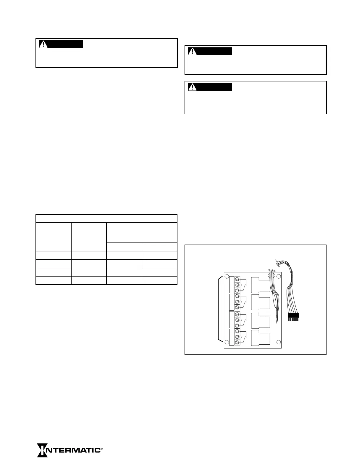
NC NO COM
NC NO COM
NC NO COM NC NO COM
ET90000 SERIES 4-CIRCUIT RELAY BOARD
CIRCUITS
1-4, 5-8, 9-12
OR 13-16,
DEPENDING
ON SLOT
USED
INDEXED PLUG FOR
CONNECTION TO
INTERFACE BOARD
6. Open the door assembly and remove and retain the
two screws just opposite of the ller panel screws.
7. Insert the new relay board assembly into the
opening, cable rst. The board should sit on top of
the brackets with its mounting holes positioned over
the holes of the previously-removed screws.
WARNING
To avoid fire, shock, or death, turn off power at circuit breaker
and test that power is off before wiring.
WARNING
To avoid fire, shock, or death, turn off power at circuit breaker
and test that power is off before wiring.
CAUTION
Some terminals in the ET90000-series electronic timer may be
energized even if the Status Screen is off. Check all terminals
and wires with an appropriate voltmeter before touching.
Bekijk gratis de handleiding van Intermatic ET90115M, stel vragen en lees de antwoorden op veelvoorkomende problemen, of gebruik onze assistent om sneller informatie in de handleiding te vinden of uitleg te krijgen over specifieke functies.
Productinformatie
| Merk | Intermatic |
| Model | ET90115M |
| Categorie | Niet gecategoriseerd |
| Taal | Nederlands |
| Grootte | 7867 MB |


