Intergas Xclusive 24 handleiding
Handleiding
Je bekijkt pagina 27 van 92
27
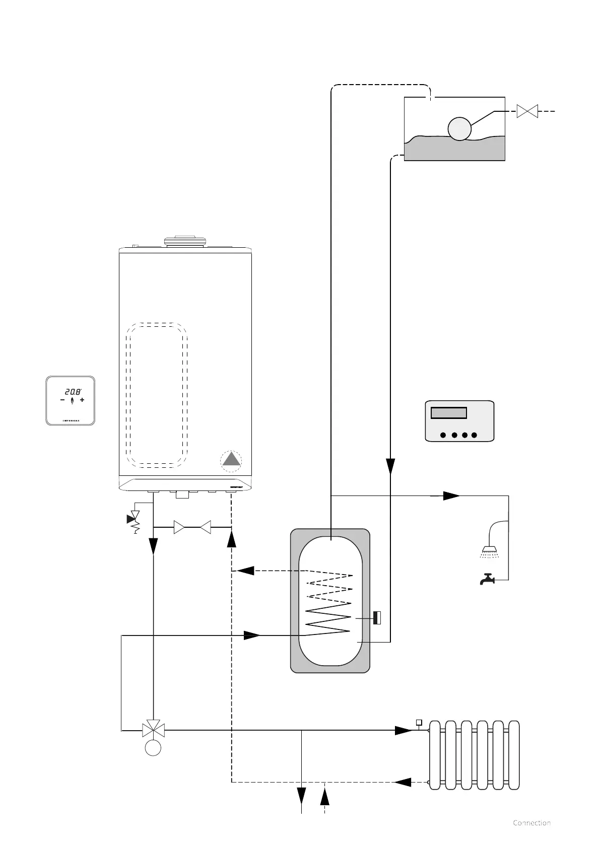
7.1.9 Y-Plan zone hydraulic diagram
m
A
B
C
Built in 6 ltr
expansion
vessel
ErP
modulating
pump
Open vented cylinder
(storage capacity to be established by
the installer
CH circuit
E
F
G
D
H
B
A
AB
Key to Hydraulic & Wiring diagrams
A. Room thermostat
B. Twin channel programmer
C. Cylinder thermostat
D. Boiler pressure reflief valve (3 Bar)
E. Hot water draw o (Gravity)
F. Mid position zone valve
G. Cold feed and expansion tank
H. System By-pass (Should be 3 meters from boiler connections)
► To alter the boiler from a combi to a system boiler please see
section §9.1.5 & §9.3
Parameter P001 change to "option 3"
Parameter P010 change to required system output %
See §9.5 for minimum permissible water circulation through the boiler
heat exchanger.
Bekijk gratis de handleiding van Intergas Xclusive 24, stel vragen en lees de antwoorden op veelvoorkomende problemen, of gebruik onze assistent om sneller informatie in de handleiding te vinden of uitleg te krijgen over specifieke functies.
Productinformatie
| Merk | Intergas |
| Model | Xclusive 24 |
| Categorie | Niet gecategoriseerd |
| Taal | Nederlands |
| Grootte | 12726 MB |


