IFM SUH701 handleiding
Handleiding
Je bekijkt pagina 19 van 39
Ultrasonic flow meter SUH1xx SUH22x SUH3xx SUH42x SUH5xx SUH6xx SUH7xx SUH8xx
19
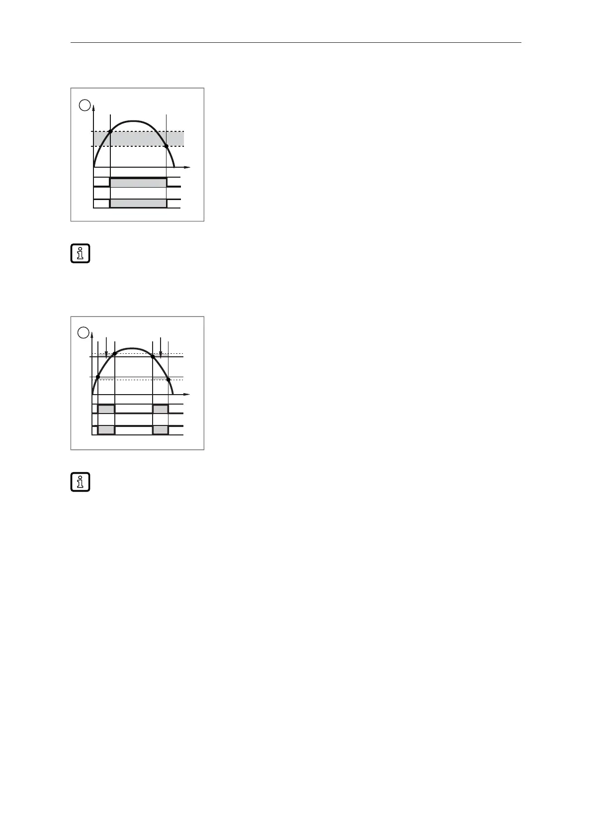
Hysteresis function:
SP
t
Hno
HY
Hnc
rP
1
0
1
0
1
Fig.8: Hysteresis function
1: Process value
t: Time
SP: Set point
rP: Reset point
HY: Hysteresis
Hno: Hysteresis function NO (normally open)
Hnc: Hysteresis function NC (normally closed)
When the hysteresis function is set, the set point [SP] and the reset point [rP] are set. The rP
value must be lower than the SP value. The difference between SP and rP is at least 0.5 % of
the final value of the measuring range (= hysteresis). If only the set point is changed, the reset
point is changed automatically; the difference remains constant.
Window function:
FE FE
FH
HY
HY
t
Fno
Fnc
FL
1
0
1
0
1
Fig.9: Window function
1: Process value
t: Time
FH: Upper limit value
FL: Lower limit value
HY: Hysteresis
FE: Window area
Fno: Window function NO (normally open)
Fnc: Window function NC (normally closed)
When set to the window function, the window high [FH] and the window low [FL] are set. The
difference between FH and FL is at least 0.5% of the final value of the measuring range. FH and
FL have a fixed hysteresis of 0.25% of the final value of the measuring range. This helps keep
the switching status of the output stable if the flow rate varies slightly.
Parameters to be set:
[oux]= [Hno], [Hnc], [Fno], [Fnc]; [SPx]; [rPx]; [FHx]; [FLx]
9.2.2 Switching signal Diagnosis
The unit features an integrated diagnostic function. When using the diagnostic function, the output is
used exclusively for diagnostic message output, which it indicates by a switched signal.
The switching output is switched on in normal operation (normally closed). If the device detects a
diagnostic case, the output will be switched off.
Diagnostic cases include:
• Reversal of the direction of flow (Ò Switching signal for flow direction/19)
• Low signal quality/ no signal (Ò Switching signal for signal quality/20)
9.2.2.1 Switching signal for flow direction
A flow direction change can be monitored by providing a switching signal.
An arrow with the text “flow direction” on the device indicates the positive flow direction. The direction
of the flow measurement can be reversed using the parameter [Fdir].
Bekijk gratis de handleiding van IFM SUH701, stel vragen en lees de antwoorden op veelvoorkomende problemen, of gebruik onze assistent om sneller informatie in de handleiding te vinden of uitleg te krijgen over specifieke functies.
Productinformatie
| Merk | IFM |
| Model | SUH701 |
| Categorie | Niet gecategoriseerd |
| Taal | Nederlands |
| Grootte | 3147 MB |


