IFM DTI921 handleiding
Handleiding
Je bekijkt pagina 25 van 46
DTI801 DTI901 DTI911 DTI921
25
9.6 Operating mode "EPC LIST
In the operating mode "EPC LIST", a list with all ID tags in the detection field is generated by setting
the Cmd start bit. The number of detected ID tags is displayed in the field "Total Number of Tags". A
process image with the following content is created for each ID tag:
• the RSSI value,
• the length of the EPC and
• the EPC.
The block counter indicates the current ID tag in the list. By incrementing the block counter in the
process data output image, the controller switches to the next ID tag. As confirmation, the value of the
block counter is mirrored by the device.
After all ID tags of the list have been transmitted, a new list is created by setting the Cmd start bit
again.
The list is a snapshot and will only be updated by setting the Cmd start bit again.
The RSSI value is a signed integer value. For example, "0xD6" corresponds to the RSSI value
"-42 dBm".
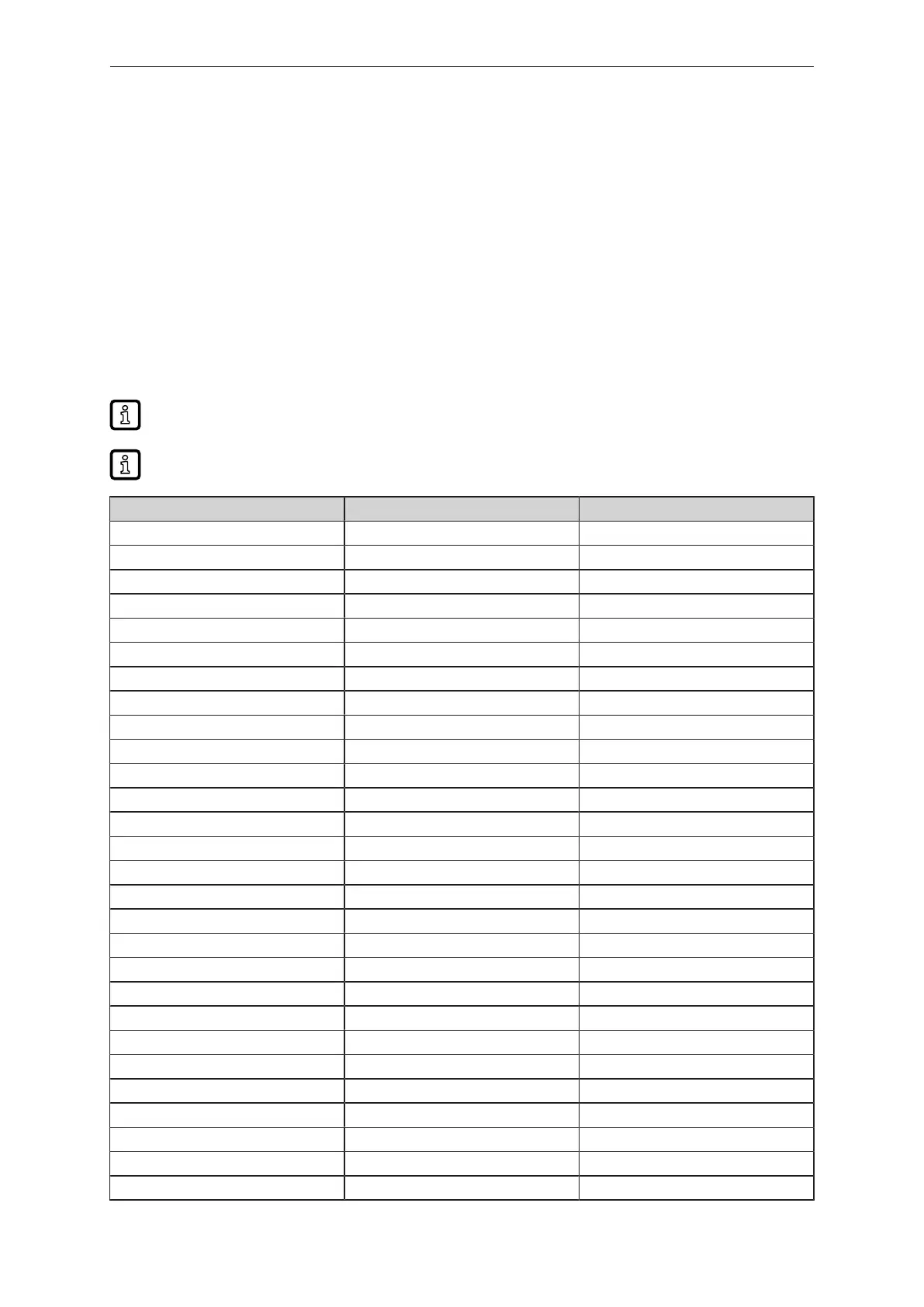
Byte Process data output Process data input
0 command value = 0x04 command value = 0x04
1 status status
2 ignored RSSI
3 ignored length of EPC
4 ignored EPC 0
5 ignored EPC 1
6 ignored EPC 2
7 ignored EPC 3
8 ignored EPC 4
9 ignored EPC 5
10 ignored EPC 6
11 ignored EPC 7
12 ignored EPC 8
13 ignored EPC 9
14 ignored EPC 10
15 ignored EPC 11
16 ignored EPC 12
17 ignored EPC 13
18 ignored EPC 14
19 ignored EPC 15
20 ignored 0x00
21 ignored 0x00
22 ignored 0x00
23 ignored 0x00
24 ignored 0x00
25 ignored 0x00
26 ignored 0x00
27 ignored 0x00
Bekijk gratis de handleiding van IFM DTI921, stel vragen en lees de antwoorden op veelvoorkomende problemen, of gebruik onze assistent om sneller informatie in de handleiding te vinden of uitleg te krijgen over specifieke functies.
Productinformatie
| Merk | IFM |
| Model | DTI921 |
| Categorie | Niet gecategoriseerd |
| Taal | Nederlands |
| Grootte | 3980 MB |


