Icom IC-7760 handleiding
Handleiding
Je bekijkt pagina 90 van 100
13-1
BASIC MANUAL
13
CONNECTOR INFORMATION
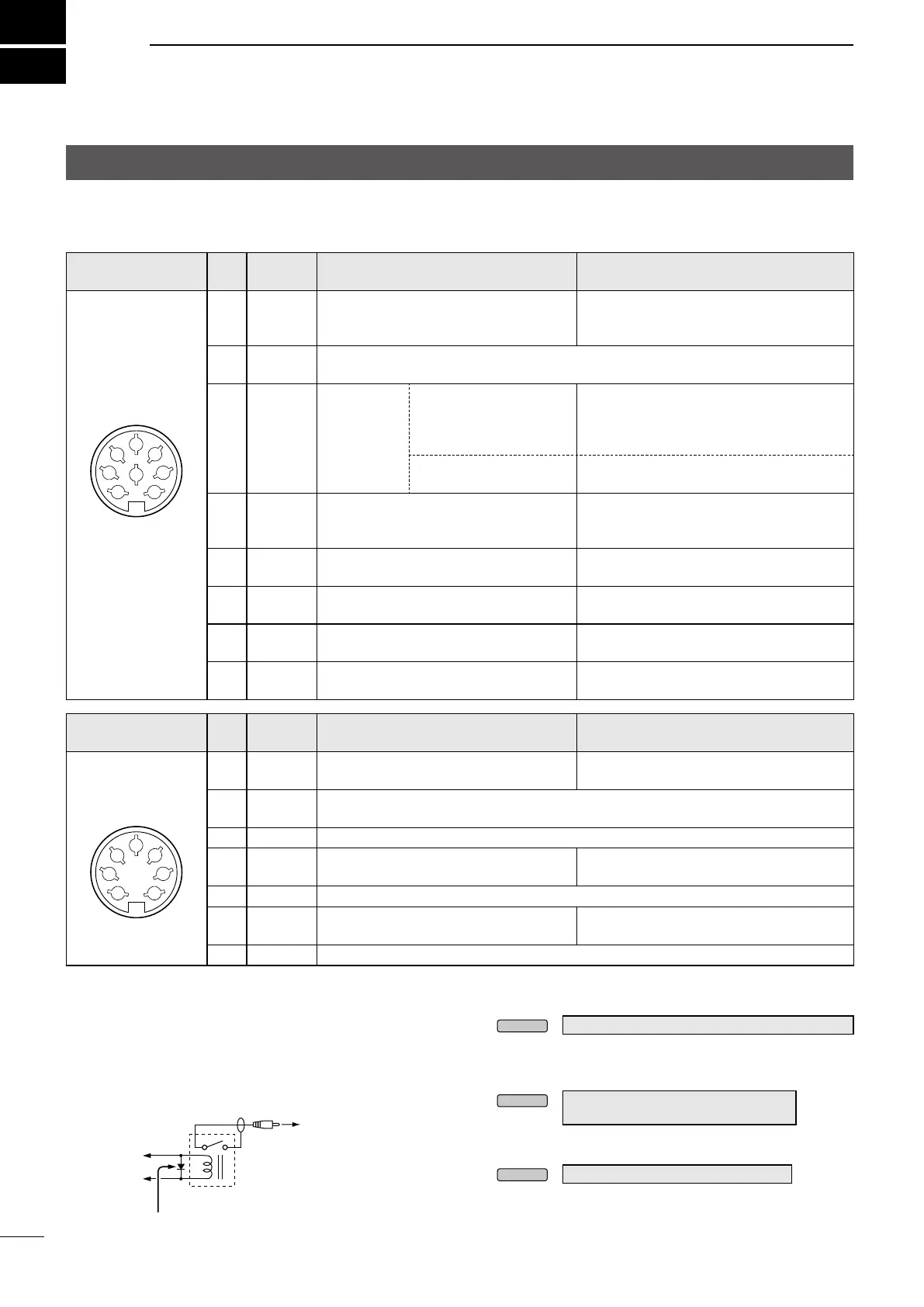
D ACC sockets
Connect to devices to control an external unit or to control the transceiver.
ACC 1
Pin
No.
Name Description Specications
1 RTTY Controls RTTY keying.
High level: More than 2.4 V
Low level: Less than 0.6 V
Output current: Less than 2 mA
2 GND
Connects to ground.
Connected in parallel with ACC 2 pin 2.
3 SEND
Input/output
pin.
Connected in
parallel with
ACC 2 pin 3.
An external unit controls
the transceiver. When this
pin goes to ground, the
transceiver transmits.
Input voltage (RX): 2.0 ~ 20.0 V
Input voltage (TX): –0.5 ~ +0.8 V
Current ow: Less than 20 mA
The pin goes low when
the transceiver transmits.
Output voltage (TX): Less than 0.1 V
Current ow: Less than 200 mA
4 MOD
Modulator input.
Connects to the internal modulator
circuit.
Input impedance: 10 kΩ
Output level: 100 mV rms*
2
5
AF/IF 12k*
3
Fixed AF detector or receive IF (12 kHz)
signal output.
Output impedance: 4.7 kΩ
Output level: 100 ~ 300 mV rms*
4
6 SQL S
Squelch output.
Grounded when the squelch opens.
SQL open: Less than 0.3 V/5 mA
SQL closed:
More than 6.0 V/100 μA
7 15 V
15 V output when power is ON.
Connected in parallel with ACC 2 pin 7.
Output current: Less than 1A
8 ALC
ALC voltage input.
Connected in parallel with ACC 2 pin 5.
Input impedance: 10 kΩ
Input level: –4 ~ 0 V
ACC 2
Pin
No.
Name Description Specications
1 8 V Regulated 8 V output.
Output voltage: 8 V ±0.3 V
Output current: Less than 10 mA
2 GND
Connects to ground.
Connected in parallel with ACC 1 pin 2.
3 SEND*
1
Same as ACC 1 pin 3.
4 BAND
Band voltage output.
(Varies with the selected amateur band)
Output voltage: 0 ~ 8.0 V
5 ALC Same as ACC 1 pin 8.
6 TRV
Activates [X-VERTER] input/output when
“HIGH” voltage is applied.
Input impedance: More than 10 kΩ
Input voltage: 2 ~ 15 V
7 15 V Same as ACC 1 pin 7.
RF Deck
Rear panel view
8-pin
Rear panel view
7-pin
*
1
When the SEND terminal controls an inductive load, such
as a relay, a counter-electromotive force can malfunction or
damage the transceiver. To prevent this, we recommend adding
a switching diode, such as a 1SS133, on the load side of the
circuit to absorb the counter-electromotive force.
LWhen the diode is added, a delay in relay switching may
occur. Be sure to check its switching action before operating.
*
2
You can change the MOD input level.
L100 mV rms is at 50% as the default.
MENU
»
SET > Connectors > MOD Level > ACC MOD Level
*
3
You can change the AF/IF (IF=12 kHz) settings to output a 12 kHz
IF signal. In that case, you can listen to DRM communication with
the application software receiver that is installed onto your PC.
MENU
»
SET > Connectors > ACC AF/IF Output >
Output Select
*
4
You can change the AF/IF (IF=12 kHz) output level.
LApproximately 200 mV rms is at 50% as the default.
MENU
»
SET > Connectors > ACC AF/IF Output
1
2
3
4
5
6
7
8
1
2
3
4
5
6
7
3
SEND
7
15 V
Example: ACC 1/2 socket
To a non-Icom linear
amplier
Switching diode
Relay
Bekijk gratis de handleiding van Icom IC-7760, stel vragen en lees de antwoorden op veelvoorkomende problemen, of gebruik onze assistent om sneller informatie in de handleiding te vinden of uitleg te krijgen over specifieke functies.
Productinformatie
| Merk | Icom |
| Model | IC-7760 |
| Categorie | Niet gecategoriseerd |
| Taal | Nederlands |
| Grootte | 18538 MB |


