Ibiza Sound COMBI-FX4 handleiding
Handleiding
Je bekijkt pagina 3 van 46
Code: 16-2064
3
https://ibizashop.eu/
INSTALLATION
The unit should be mounted via its screw holes on the bracket. Always ensure that the unit is rmly xed to
avoid vibration and slipping while operating. Always ensure that the structure to which you are attaching the
unit is secure and able to support a weight of 10 times of the unit’s weight. Also always use a safety cable that
can hold 12 times the weight of the unit when installing the xture.
The equipment must be xed by professionals at a place where is out of the reach of people and where nobody
can pass by or under it.
FIXTURE LINKING
You will need a serial data link to run light shows of one or more xtures using a DMX-512 controller or to run
synchronized shows on two or more xtures set to a master/slave operating mode. The combined number of
channels required by all xtures on a serial data link determines the number of xtures that the data link can
support.
Important: Fixtures on a serial/data link must be daisy chained in one single line. Maximum recommended
serial data link distance: 100 meters (1640 ft.) Maximum recommended number of xtures on a serial data link:
32 xtures
CABLE CONNECTORS
Cabling must have a male XLR connector on one end and a female XLR connector on the other end.
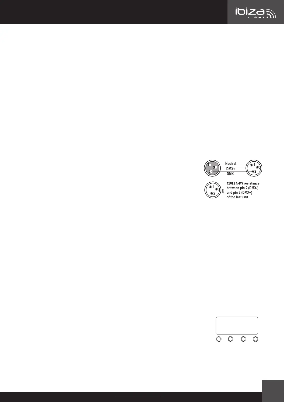
DMX CONNECTOR CONFIGURATION
Termination reduces signal errors. To avoid signal transmission problems and interfe-
rence, it is always advisable to connect a DMX signal terminator.
CAUTION
Do not allow contact between the common and the xture’s chassis ground. Groun-
ding the common can cause a ground loop, and your xture may perform erratically.
Test cables with an ohm meter to check correct polarity and to make sure the pins
are not grounded or shorted to the shield or each other.
SETTING UP A DMX SERIAL DATA LINK
1. Connect the (male) 3 pin connector side of the DMX cable to the output (female) 3 pin connector of the
controller.
2. Connect the end of the cable coming from the controller which will have a (female) 3 pin connector to the
input connector of the next xture consisting of a (male) 3 pin connector.
3. Then, proceed to connect from the output as stated above to the input of the following xture and so on.
DMX ADDRESS SETTING
Each xture must have a specic starting address. When receiving signal transmission, every xture will receive
channels control signals for its own starting address.
The user can set several xtures to the same address or set up a separate address for every device.
If more than one xture is set to the same address, all of them receive the same DMX channels signals. All
connected xtures are jointly controlled; the controller can’t control a device separately.
If every device is set to a dierent address, it will receive dierent DMX signals corresponding to its starting
address.
This device has 6 channels. So, the rst device’s starting address is set 1, second is 7 (1+6), third is 13 (7+6)
and so on.
CONTROL PANEL
UP
DOWN
MENU ENTER
8.8.8.8.
The control panel is the mechanism for conguring the settings. It has a small LCD
screen and four buttons, which are described below.
BUTTON FUNCTIONS
MENU: Scrolls through the rst level of options, or exits from the current menu or func-
tion
UP: Navigates upward through the menu list or increases the numeric value when in a function
DOWN: Navigates downward through the menu list or decreases the numeric value when in a function
ENTER: Enables the currently displayed menu or sets the currently selected value in to the current function
Bekijk gratis de handleiding van Ibiza Sound COMBI-FX4, stel vragen en lees de antwoorden op veelvoorkomende problemen, of gebruik onze assistent om sneller informatie in de handleiding te vinden of uitleg te krijgen over specifieke functies.
Productinformatie
| Merk | Ibiza Sound |
| Model | COMBI-FX4 |
| Categorie | Verlichting |
| Taal | Nederlands |
| Grootte | 6102 MB |


