Hendi 231227 handleiding
Handleiding
Je bekijkt pagina 10 van 32
2.5 CHARACTERISTICS OF FEED WATER
Feed water must be:
• Drinkable and clean (SDI 1)
• Temperature must be between 6° and 25°C
• Hardness must be below 900 ppm CaCO
3
(90°f)
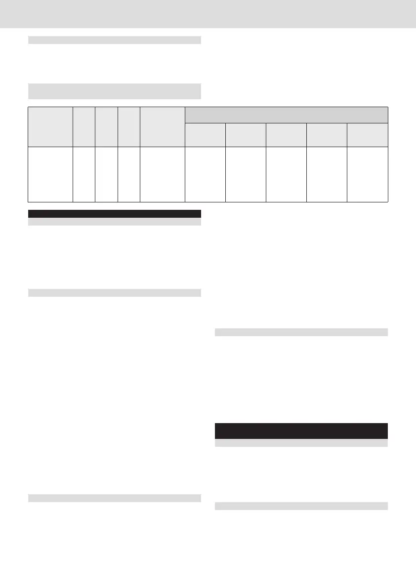
2.6 EQUIPMENT PERFORMANCE
BASED ON WATER HARDNESS
3. INSTALLATION
3.1 PACKAGING
• Before the installation, check that the equipment was not
damaged by the transport and does not show any anomaly.
If in doubt, ask your seller, whose information is written on
the back of this manual.
• Don’t throw the package away for some time, being careful
to keep any dangerous or small parts of the package away
from children.
3.2 CHOOSING THE PLACE OF INSTALLATION
• Ensure that any other water treatment machine is not pre-
sent upline of the place of installation.
• Ensure that feed water comes from a drinking water pipe.
We recommend checking the chemical and physical para-
meters of the drinking water as well as its hardness before
installation.
• Install the equipment near a floor sink, to dispose of the
waste water produced by the regeneration.
• Install the equipment in a dry place that can be easily ac-
cessible to maintain, regenerate and clean the equipment.
Do not install the equipment in dirty and unhygienic places,
or in any place difficult to clean.
• Ensure that room temperature in the place of installation is
between 4°C and 35°C.
• Keep away from corrosive or acid products.
• Do not install in places where electric safety norms or per-
sonal safety norms are openly disregarded.
• Hydric pressure must not be under 0.1 Mpa (1 bar) or over
0.8 Mpa (8 bar). (We recommend at least 3 or 4 bar)
• If hydric pressure is over 8 bar, it is necessary to install a
pressure adaptor.
• Salt packages or boxes must not be kept in humid places
or in direct contact with the floor: keep it, for example, on a
wooden pallet.
3.3 CONNECTION TO THE WATER SYSTEM (fig.1)
The connection of the equipment to the water system must
be done according to all applicable norms, following the in-
structions of the manufacturer and qualified personnel.
During the installation use pipes, hoses, valves and com-
ponents which comply with the applicable Italian norm on
hygienic safety, the Ministerial Decree 174/2004. They must
be kept in their sealed package until the moment of instal-
lation to preserve their hygienic safety. It is forbidden to use
components that are not suitable for drinking water contact,
or components which hygienic safety was compromised, as
they could corrupt the quality of treated water and the equi-
pment itself.
Connect the water inlet (fig. 1, A) and outlet (fig.1, B) to the
connection joints (fig.3) of the water softener, tightening them
safely.
Ensure that:
• The water inlet and outlet pipes (fig. 1, A and B) comply with
the norms on drinking water pipes.
• The water inlet pipe (fig 1, A) has an internal diameter of at
least 7 mm.
• A standard tap (fig. 1, M) must be installed by the user
between the water system and the water softener, to ensure
that water flow can be interrupted in case of necessity.
• Install on the water outlet a check valve (fig. 1, I) (DVGW,
DIN 1988 T2) to protect the water softener from a reverse
flow of hot water that could cause damage.
• Install a tap to take a sample of the outlet water, to test its
hardness.
All pipes must be free, not crushed or constricted.
3.4 CONNECTION TO THE DRAIN SYSTEM
Waste water resulting from the regeneration is funnelled into
the floor sink by the flexible pipe (fig.1, F) included in the
package.
Warning: keep the drain pipe suspended over and not
immersed in the water of the sink (fig. 1, N).
At the end of the installation, before opening the wa-
ter inlet and outlet taps (fig. 1, C-D), rinse the resins as
explained in the chapter “Activation and instructions for
the regeneration”.
4. ACTIVATION AND INSTRUCTIONS
FOR THE REGENERATION
4.1 RINSING THE RESINS (fig. 2)
Put the water outlet pipe in the floor sink.
Turn the tap levers on the left and open the standard tap to
let the water in.
Let the water flow until it is clear, then close the standard tap
(fig.1, M) and connect the water outlet pipe to the machine of
your choice.
4.2 PERIODIC REGENERATION (fig. 4)
• Position B (DEPRESSURIZATION MODE)
1) Put the depressurization pipe in a bucket (fig. 1, E and fig.
4, position B)
2) Turn the tap levers on the right and wait until depressuriza-
tion.
3) Remove the lid (fig. 1, G) and add the required quantity of
10 Instruction Manual Water Softener
ENGLISH
instruction manual
Water Softener
20°f 30°f 40°f 50°f 60°f
11°d 16°d 22° d 28°d 33°d
200ppmCaCO
3
300ppmCaCO
3
400ppmCaCO
3
500ppmCaCO
3
600ppmCaCO
3
LITRES OF WATER SOFTENED, BASED ON HARDNESS
WEIGHT
[kg]
RESIN
[l]
SALT/RIG.
[kg]
h
[mm]
MODEL
400
7,5
5,6
1
1680
8,4
1120
840
672
560
Bekijk gratis de handleiding van Hendi 231227, stel vragen en lees de antwoorden op veelvoorkomende problemen, of gebruik onze assistent om sneller informatie in de handleiding te vinden of uitleg te krijgen over specifieke functies.
Productinformatie
| Merk | Hendi |
| Model | 231227 |
| Categorie | Niet gecategoriseerd |
| Taal | Nederlands |
| Grootte | 5270 MB |


