Hayward Control Station NG handleiding
Handleiding
Je bekijkt pagina 20 van 74
EN
EN
English
English
Only use spare parts supplied by Hayward brands
®
Only use spare parts supplied by Hayward brands
®
Page 16 on 20 Page 17 on 20Control Station NG Control Station NG
6f. Installing and starting up the free chlorine option (membrane sensor)
1 Calibration of the free chlorine sensor equipped with a membrane: It is
recommended to do this once a week during the season the pool is in use.
2 Before beginning the calibration, measure the pool free chlorine (in ppm) by
performing a DPD1 analysis and click on Test DPD1.
3 Step 1 of 3: Enter the value measured during the DPD1 analysis and press OK.
4 Step 3 of 3: Press OK to validate the calibration.
1 Open the cover and connect the CL CHIP card to the CL slot (see section 3C).
The chlorine reading and the Measures menu will be displayed automatically, to
congure the setpoint and carry out the calibration.
2 Congure the 4-20 mA membrane sensor in the service menu.
3 Place the sensor in a bypass, following the sensor instructions.
4 Connect the 3 cables of the oater to the extension circuit board (see section 3C).
5 Connect the 2 cables of the sensor to the extension circuit board (see section 3C).
6 Leave the sensor to polarise for at least 24h.
7 Start sensor calibration after 24h in operation.
i
The ow through the transparent mount must be constant to ensure optimum
reading.
i
The sensor has a lifetime of 1 year. We recommend calibrating it every month
during the season the pool is in use.
•
Always begin the calibration procedure with a calibration reset.
•
Please contact your dealer for conguration of the free chlorine sensor equipped with a membrane.
•
We recommend calibrating the free chlorine sensor with a high chlorine level: between 1ppm and 1.2ppm.
1 2 4
mA
ppm Cl2
4
5
10
12 20
3
0
1 Calibration of free chlorine: It is recommended
to do this once a month during the season the
pool is in use.
2 Calibration using reference values (DPD1
photometer): Follow the 6-step instructions that
appear on the display screen (points 4 to 7).
3 Manual calibration: Open the water intake and
wait until the free chlorine value displayed on the
unit screen is stable. With the up/down buttons,
adjust the value displayed until it coincides with
the free chlorine value measured during the
DPD1 analysis (in ppm), then press OK.
4 Step 1 of 6 - CL calibration of 1st point
(0 ppm): Stop the ow of water through the
sensor and wait until the value displayed on the
unit screen drops below 0.10 ppm (between
5 and 60 minutes). Press OK when the value is
close to 0.
5 Step 3 of 6 - CL calibration of 2nd point:
Open the water intake to a rate of 80-100 litres/h
then wait until the free chlorine value is stable
(between 5 and 20 minutes). Press OK when the
value is stable.
6 Step 5 of 6 - With the up/down buttons, adjust
the displayed value until it coincides with the
free chlorine concentration measured during the
DPD1 analysis (in ppm) then press OK.
7 Step 6 of 6 - If this screen does not appear,
repeat the calibration process.
4.1 4.2 4.3
5.1 5.2 6 7
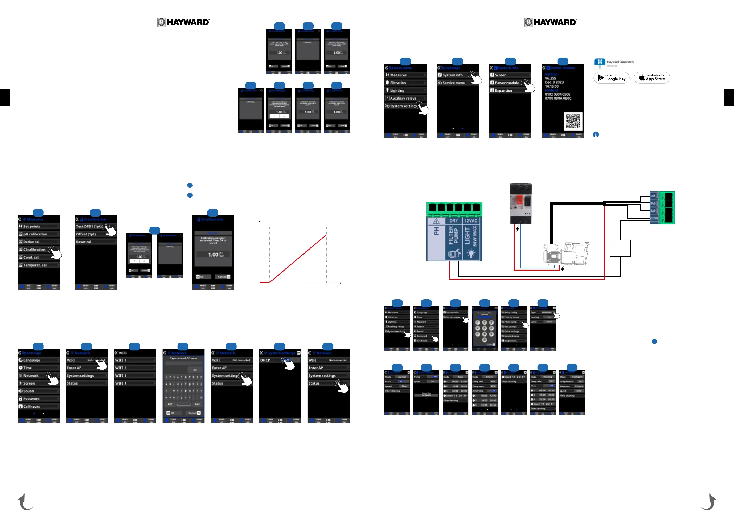
6g. Installing the WiFi or Ethernet module
1 Internet: Once the module is connected, switch on the device. A Network menu
appears in the Settings menu.
2 Wi: Select the Wi menu to start an automatic search for available networks.
3 Choose the relevant available network.
4 Enter the password for this network via the keyboard. To conrm, press OK.
5 Conguration: If you want to congure your connection manually or if automatic
conguration fails, you can change the network parameters in this menu.
6 The default setting “DHCP = ON” must be left as it is.
7 Status: Displays information about your current connection.
1 Open the cover and connect the WiFi module to the WIFI slot (see section 3C). The Network menu appears automatically in the Settings menu. The power LED remains
steady and the connection LED ashes
2 3 4 5 6
7
6h. Installing and starting up a variable-speed pump
•
To install and control a 3-speed pump, please contact your dealer.
2 53
6
61
4
4 6
3 Enter the service menu from
the conguration menu.
4 Enter the password (contact
your dealer to obtain the
password).
5 Enter the pump type menu.
6 Select the type of pump.
The default pump type is
“standard” (single-speed).
When using a variable-speed
pump, select variable speed
A, B or C. In this case, one
of the 3 default speeds (V1,
V2, V3) can be assigned to
the heating and for when the
cover is closed.
i
Select Var. speed A for a
Hayward variable-speed
pump.
After connecting a variable speed pump, you can assign a
different speed individually to each ltration period, as required.
V1: S, V2: M, V3: F
Filter cleaning: To clean the lter with a variable speed pump, it is
best to use the highest speed (V3).
Diagram of variable-speed pump installation on the Control Station NG
3 51 2
Thermal circuit breaker / Switch
Pump
V1
V2
V3
black
red
N
P
Q
O
H MLKJI
•
Cable must
be added
•
When the module is connected to the Wi network and
the two LEDs are continuously on (steady), you can register at
poolwatch.hayward.fr or on the Hayward Poolwatch app.
Get your Node ID (steps 8 to 11) and follow the registration
process. You can scan the QR code directly in the app to
register your pool. Once you have registered, you can monitor
all your Control Station NG parameters remotely with Hayward
PoolWatch.
Only WiFi networks with a frequency of 2.4 GHz are
accepted by the module.
98 10 11
1
Bekijk gratis de handleiding van Hayward Control Station NG, stel vragen en lees de antwoorden op veelvoorkomende problemen, of gebruik onze assistent om sneller informatie in de handleiding te vinden of uitleg te krijgen over specifieke functies.
Productinformatie
| Merk | Hayward |
| Model | Control Station NG |
| Categorie | Niet gecategoriseerd |
| Taal | Nederlands |
| Grootte | 35381 MB |
