Handleiding
Je bekijkt pagina 9 van 36
9CWBPSM-0225
English
INSTALLATION
NOTICE
When shipped during cold weather months, store unit in
proper ambient temperature environment for 10 hours to
prevent compressor and/or refrigerant line damage. If unit
is turned on and there is excessive noise and vibration,
turn off immediately and allow additional warm up time.
Do not locate unit in an area subject to excessive
temperatures or grease from grills, fryers, etc. Excessive
temperatures could cause damage to the unit.
All Slim Refrigerated Drop-In Wells are shipped in a shipping
frame for protection and stability. Keep the unit in the shipping
frame until the unit and the installation site are completely
prepared for the unit to be installed.
1. Remove all external packaging from the unit.
2. Remove tape, protective packaging, and literature from all
surfaces of the unit.
NOTE: To prevent delay in obtaining warranty coverage, complete
online warranty registration. See the IMPORTANT
OWNER INFORMATION section for details.
Preparing the Installation Site
Survey the installation site and determine if adjustment to the
orientation and/or position of the condensing unit is necessary.
Take into account the need for louvered or grill-style openings in
the cabinetry to provide proper ventilation for the unit as well as
access to the control panel. One of these ventilation openings
must be in front of the condensing coils with the other on the
opposite side. If multiple refrigerated wells are installed in the
same counter, each unit should intake cool air and expel hot air.
NOTE: The condensing unit cannot be moved or rotated under
the well. Damage to the refrigerant tubing will occur.
The cabinet must be enclosed on all four sides. The condensing
unit must be isolated from other electronic devices using fully
sealed partitions. The cabinet must allow access for ventillation,
control access, and maintenance/cleaning access.
1. Cut the appropriate opening in the countertop for the unit
being installed. Refer to “Countertop Cutout Dimensions”
in this section.
2. If installing the control panel remotely, cut and drill the
appropriate holes in the vertical surface where the control
panel will be installed. Refer to the “Installing the Control
Panel Remotely” procedure for cutout dimensions.
3. Cut opening in the cabinet for intake vent.
• The cutout must be 12″ x 12″ (31 x 31 cm).
• The opening for the intake must be no further than 5'
(1524 mm) from the condenser coils.
4. Cut opening in the cabinet for exhaust vent.
• The opening for the exhaust must be cut no more than
1″ (25 mm) from cabinet floor.
• The opening should be a minimum of 12″ x 12″
(31 x 31 cm) or 144 square inches (961 square cm).
• The opening for the exhaust must be located on the
opposite side of the condensing unit.
5. Cut opening in the cabinet for access to the control panel,
if necessary. Refer to the “Installing the Control Panel
Remotely” procedure for the cutout dimensions.
6. Cut opening in the cabinet for access to the condensing
unit coils for cleaning. Louvered or grill-style panels should
be installed in the openings to protect the condensing unit.
7. Make structural modifications or add bracing underneath
the countertop to ensure the countertop will support the
weight of the unit and its contents. Make sure a minimum
2″ (51 mm) clearance will be available between the
condensing unit and any interior surface.
NOTE: The countertop must be level to ensure proper draining
of the refrigerated well.
8. Make sure a grounded electrical receptacle of the
correct voltage, size, and plug configuration is within 6′
(1829 mm) of the mounting location for the control panel.
See the SPECIFICATIONS section for details.
WARNING
FIRE HAZARD: All electrical receptacles must be at least
12″(305mm)abovethecabinetfloor.
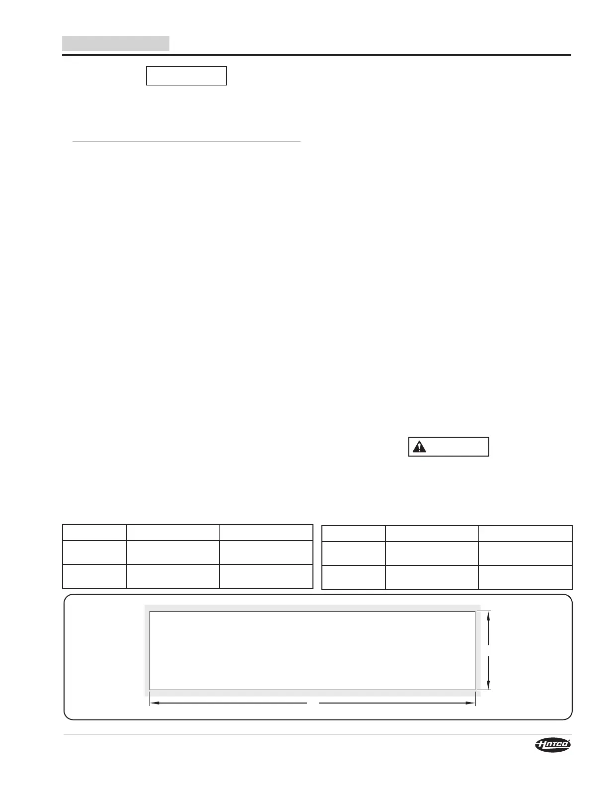
B
A
Countertop Cutout Dimensions
CWBP-S Series Countertop Cutout Dimensions
Model Width (A) Depth (B)
CWBP-S1
25-3/16″–26-1/16″
(641–662 mm)
17-1/16″–17-15/16″
(433–456 mm)
CWBP-S2
46-1/4″–47-1/8″
(1175–1196 mm)
17-1/16″–17-15/16″
(433–456 mm)
Model Width (A) Depth (B)
CWBP-S3
67-5/16″–68-1/8″
(1710–1731 mm)
17-1/16″–17-15/16″
(433–456 mm)
CWBP-S4
88-3/8″–89-3/16″
(2245–2266 mm)
17-1/16″–17-15/16″
(433–456 mm)
Bekijk gratis de handleiding van Hatco CWBP-S2, stel vragen en lees de antwoorden op veelvoorkomende problemen, of gebruik onze assistent om sneller informatie in de handleiding te vinden of uitleg te krijgen over specifieke functies.
Productinformatie
| Merk | Hatco |
| Model | CWBP-S2 |
| Categorie | Koelkast |
| Taal | Nederlands |
| Grootte | 5820 MB |


