Handleiding
Je bekijkt pagina 52 van 86
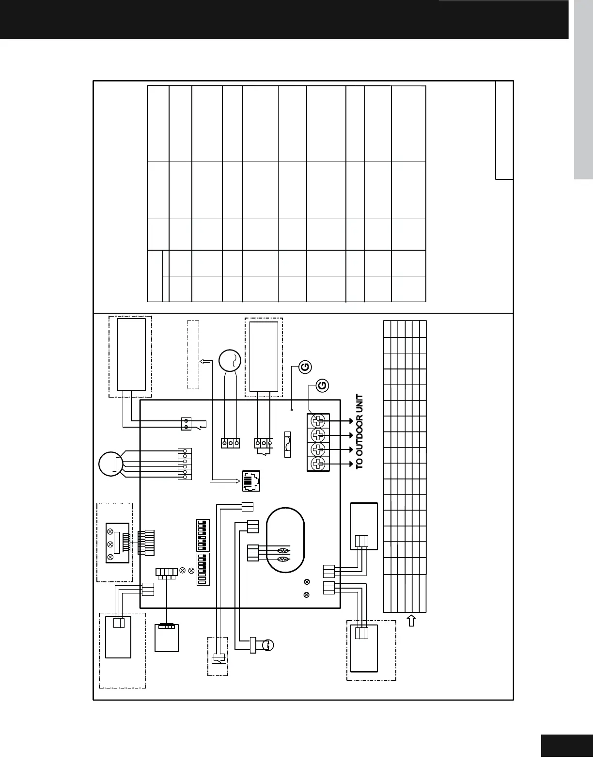
MID-STATIC DUCTED INDOOR UNITS
Í¡!#
ENGLISH
àÒÛÒ×ÐÍÒÊÐÛÊÖ
FRELAY FOR FRESH AIR
MOTOR(dry Contact
,rating-230VAC,3A) /E.A.0
FUSE
T250V 5A
&1
1(L1)
G
AC PUMP
MOTOR
DC FAN
MOTOR
AB
C
AB
C
AB
C
AB
C
Tp
Tr
CN3
CN16
ROOM CARD
FLOAT SWITCH
ON ON
YCJ-A002
CN13
CN17
INFRARED SIGNAL RECEIVER
TO RJ 45 device
CN 22-1
CN22
LED 2
LED 1
SW01
SW03
CN21
CN6
D
C
CN20
RJ45
LED3
LED4
Y/G
YL
YL
CN19
RD
RD
CN9
CN10
RD
BLK
WHT
YL
BLU
REMOTE
CENTRAL
CONTROL
ADAPTOR
2(L2) 36
Indoor unit trouble shooting
Flash times of the
indoor unit PCBA
Wired
controller
error code
Contents of
malfunction
Possible reason
LED3 LED4
0101
Malfunction of indoor
unit ambient temper-
ature sensor
Malfunction of
indoorunit pipe(coil)
temperature sensor
0202
0404
EEPROM wrong
of indoor PCB
0
7
07
Abnormal communi-
cation between
indoor and outdoor
units
08/
Abnormal communi-
cation between
wired controlleer
and indoor unit
0120C
Malfunction of
drain system
0130D
Zero cross sigal
wrong
0140E
Indoor unit DC
fan motor
abnormal
M(2) N(0)
HEX code
correspond
to decimal
(M*10+N)
Error of the
outdoor unit
See note 1,2
Note:
1.The outdoor failure can also be indicated by the indoor
unit,the checking method as follows:outdoor unit error
code=(M*10+N)-20.LED3 flash M times and LED4 flash N
times .The wired controller error display the HEX CODE which
correspond to DEC code (M*10+N).
2.To get much more details about the out door unit
failure,please refer to the outdoor
unit trouble shooting list.
NOTE:
1.Dashed
parts are opt
ional.
2.Please refer to service manual to get details of the DIP switches definition .
3.Do not change the DIP switches setting without technical support.
4.Get details from trouble shooting list about LED indication.
5.Abbreviation
˖
RD -red, W-withe,BLK-black,BLU-blue,GRN-green,YL-yellow,Y/G-yellow/greenE.A.O:
external alarm output,Tr
˖
indoor unit ambient(room) temperature sensor,Tp
˖
indoor unit pipe(coil)
temperature sensor.
6.The port CN4&CN10are dry contact output port for particular u
se,do not c
onnect other device without
technical person support.
M
M
WIRED
CONTROLLER
WIRED
CONTROLLER
123
45
6
7
8
123
45
6
7
8
CN4
P1 P2
RELAY FOR AUXILIARY
(dry contact port,contact
rating 230VAC,3A
BLU
GRN
BLU
W
RD
BLU
BLK
W
W
Factory default setting
of the DIP switches
SW1-1 SW1-2 SW1-3 SW1-4 SW1-5 SW1-6 SW1-7 SW1-8 SW3-1 SW3-2 SW3-3 SW3-4 SW3-5 SW3-6 SW3-7 SW3-8
USYM24UCDDA1
MODEL
ON ON OFF OFF OFF OFF OFF OFF OFF OFF OFF OFF OFF OFF OFF
ON
12V
COM
GND
DNG
MOC
V21
W
W
WiFi MODULE
W
DNGP
V51
PSV
GF
OFF ON OFF OFF OFF OFF OFF OFF OFF OFF OFF OFF OFF OFF
ON
OFF OFF OFF OFF OFF OFF OFF OFF OFF OFF OFF OFF
OFF
ON
OFF ON
OFF OFF OFF OFF OFF OFF OFF OFF OFF OFF OFF OFF
ON
ON
Sensor disconected,or brok-
en,or at wrong position,or
short circuit
Sensor disconected,or brok-
en,or at wrong position,or
short circuit
EEPROM chip disconected
or broken or wrong program-
med,or PCB broken
connection wires
disconected or wrong
adress setting of indoor
unit or faulty power supply
or faulty PCB
Wrong connection or wired
controller broken,or PCB
faulty
Pump motor disconnected
or atwrong position,or the
float switch disconnected or
at wrong position,or the
PCB float port short
connector disconnected
Zero cross sigal detected
wrong
DC Fan motor disconnected
or DC Fan broken or circuit
broken
USYM30UCDDA1
USYM36UCDDA1
USYM42UCDDA1
USYM48UCDDA1
OFF
ON
ON
OFF OFF OFF F OFF
ON
OF
OFF
OFF OFF OFF OFF OFF
OFF
ON
ON
ON
Y/G
CH1
31-5000936-1
Bekijk gratis de handleiding van Haier Arctic 1U3036LP2HDA, stel vragen en lees de antwoorden op veelvoorkomende problemen, of gebruik onze assistent om sneller informatie in de handleiding te vinden of uitleg te krijgen over specifieke functies.
Productinformatie
| Merk | Haier |
| Model | Arctic 1U3036LP2HDA |
| Categorie | Airco |
| Taal | Nederlands |
| Grootte | 34168 MB |


