Growatt WIT 50-100KTL3-AU handleiding
Handleiding
Je bekijkt pagina 9 van 66
1211
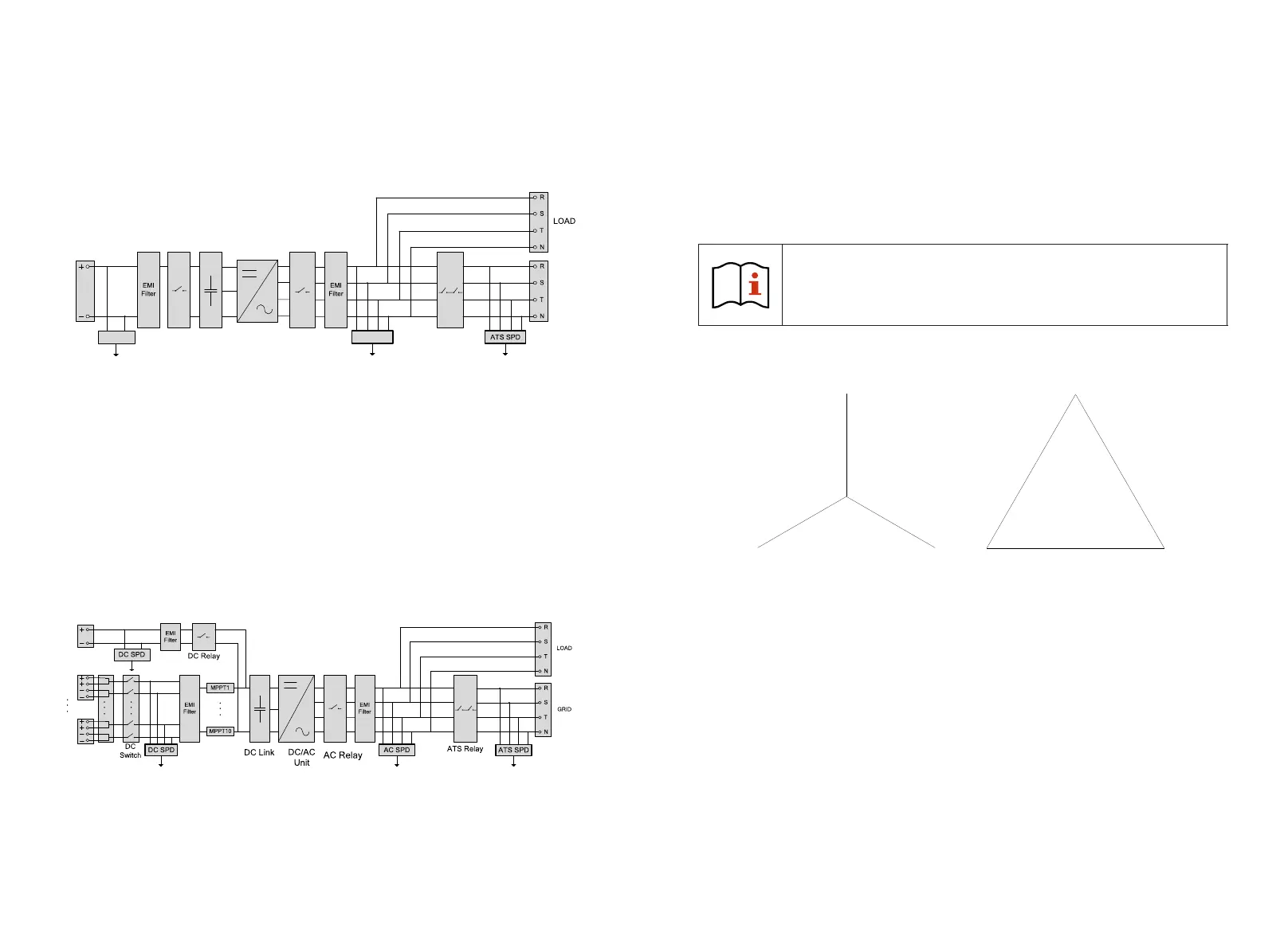
3.4.3 Operating Principle of WIT 50-100K-AE and WIT 50-100K-AU
Fig 3.10 WIT 50-100K-AE and WIT 50-100K-AU Grid-connected conceptual diagram
1> Convert battery power to AC power supply for the loads or feeding the energy to the
grid;
2> Charge the battery from the grid through a rectifier circuit;
3> Convert the battery power into AC power through the inverter circuit to provide power
to critical loads.
3.4.4 Operating Principle of WIT 50-100K-HE and WIT 50-100K-HU
1> The Hybrid Inverter receives DC inputs from PV strings which go through the MPPT
routes. The DC power is then converted into AC power through the inverter circuit to
power the loads and feed power into the grid;
2> The PV strings can supply power to charge the battery through the MPPT routes;
3> Convert battery power to AC power for the loads and feeding to the grid;
4> Charge the battery from the grid through a rectifier circuit;
5> Convert DC input from PV strings and the battery power into AC power through the
inverter circuit to power critical loads.
Fig 3.11 WIT 50-100K-HE and WIT 50-100K-HU Grid-connected conceptual diagram
NOTE: WIT 50K-HE/-HU models have 7 MPPT routes. WIT 63K-HE/-HU models have 8
MPPT routes. WIT 75K-HE/-HU and WIT 100K-HE/-HU models have 10 MPPT
routes.
3.5 StoringtheWITInverter
2> Keep the storage temperature from –30°C to +70°C and the humidity from 0%–95%
RH.
3> A maximum of three WIT Inverters can be stacked. Do not stack inverters without
package.
1> Put the WIT Inverter in the original package and place it in a dry and well-ventilated
place.
4> If the WIT Inverter has been long-term stored, inspections and tests should be
conducted by qualified personnel before installation.
Wrong time and date may occur if the WIT Inverter has been stored for
over one month. Fix the time and date before connecting the WIT
Inverter to the grid. For details, see 7.2 Commissioning the WIT
Inverter.
3.6 Supported Grid Types
Fig3.12 380V /400V system(type Y/△)
3.7 AFCI Function
An AFCI, or Arc-Fault Circuit Interrupter, is a solution designed to detect and mitigate the
risk of electrical arcing in a photovoltaic (PV) system, supported by intelligent arc
detection algorithm. Arcing can occur when there is a high voltage breakdown in the
electrical insulation or when conductive materials come into contact with each other.
This can pose a fire hazard and damage the system components. The AFCI continuously
monitors the system for potential arc faults and, if detected, interrupts the circuit to
prevent a fire or other damage. AFCIs are required by the National Electrical Code (NEC)
in certain parts of a PV system, such as the DC side of the inverter, to improve safety and
reduce the risk of fires.
Grid connection modes for WIT 50-100K Storage/Hybrid Inverters are shown in Figure 3.12.
BAT+
BAT-
DC Relay
DC Link
DC/AC
Unit
AC Relay
GRID
ATS Relay
DC
SPD
AC
SPD
PV1
BAT
PV10
220V/230V/240V
3
8
0
V
/
4
0
0
V
/
4
1
5
V
380V/400V/415V
3
8
0
V
/
4
0
0
V
/
4
1
5
V
N
3P4W
3P3W
3.7.1 AFCI function description
NOTE:
1. The AFCI Function of the WIT Inverter is disabled by default. If you want to enable the
AFCI, please contact Growatt support.
2. Do not connect the Maximum Power Point Trackers (MPPTs) on the DC side in parallel as
it might trigger the AFCI mistakenly.
Bekijk gratis de handleiding van Growatt WIT 50-100KTL3-AU, stel vragen en lees de antwoorden op veelvoorkomende problemen, of gebruik onze assistent om sneller informatie in de handleiding te vinden of uitleg te krijgen over specifieke functies.
Productinformatie
| Merk | Growatt |
| Model | WIT 50-100KTL3-AU |
| Categorie | Niet gecategoriseerd |
| Taal | Nederlands |
| Grootte | 14891 MB |


