Growatt MAX 250KTL3-X HV handleiding
Handleiding
Je bekijkt pagina 14 van 37
6>Connect the positive and negative poles to inverter terminals, different inverter's
maximum single string input current please refer to following table:
Inverter model
Max. single string input current
MAX 175-253KTL3-X HV
1 5 A * 2
7>Cable specifications:
Inverter model
Cross-sectional
area(mm²)
Recommendation
(mm²)
Cable outer
diameter(mm)
MAX 175-253KTL3-X HV
4-6
4
4.5-7.8
Notice:1.Under any circumstance, the total current of all strings cannot exceed the
inverter's maximum current
2. Do not touch any working solar panels.
3. Make sure the cable is unbroken.
6.3 Connection Of Communication Cables
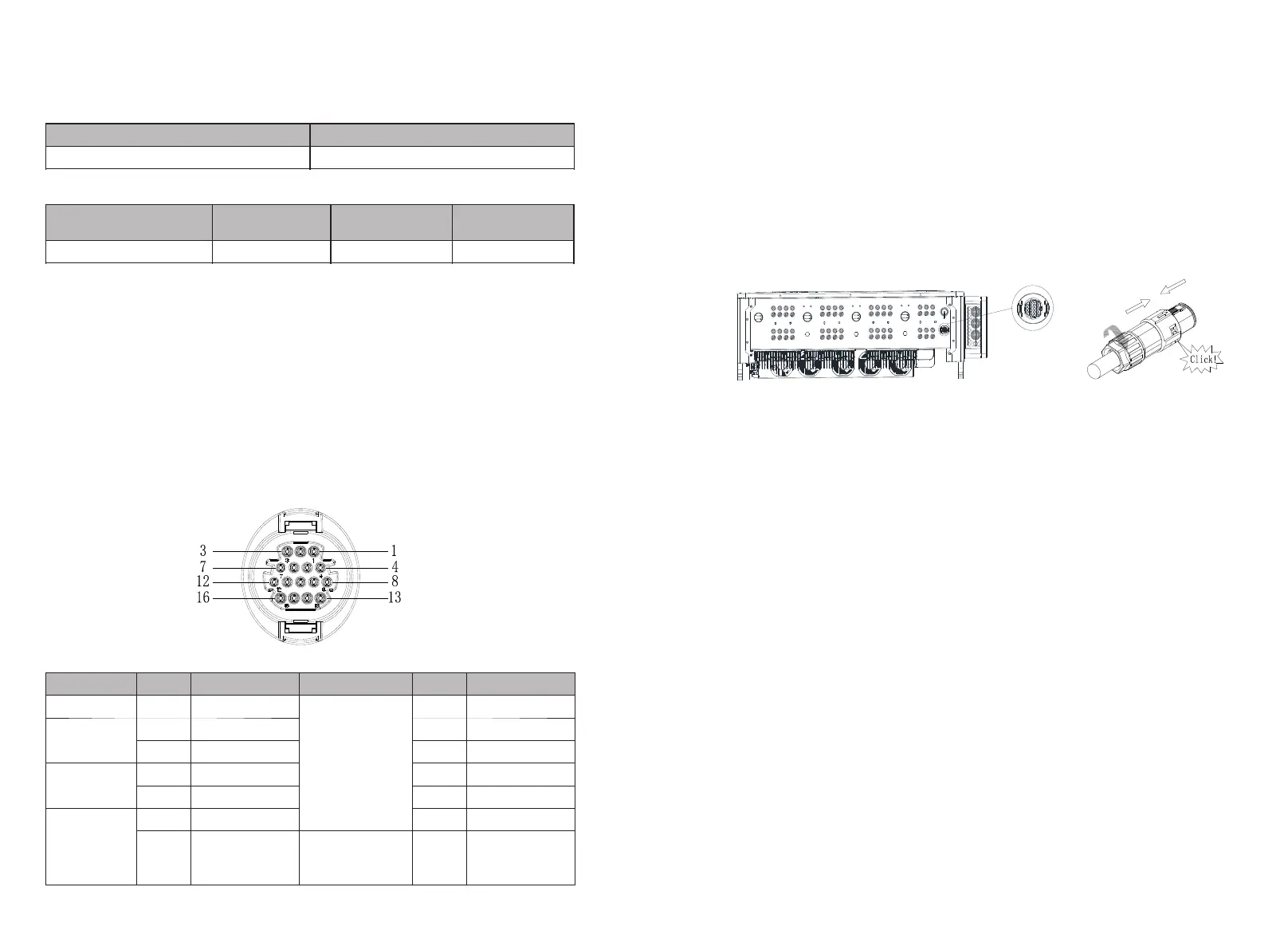
6.3.1 RS485 port
Rs485 can carry out single-machine communication or multi-machine (32pcs)
longdistance (500 meters) high-speed (baud rate 38400) communication. It is
recommended to use twisted-pair shielded wire for RS485 communication line. For
single-machine communication, the communication line can be connected to pin 3/4,
and its shielding layer can be connected to pin 1. When multiple machines are connected
in parallel, two RS485-1 ports can be connected at the same time. When used, the
shielding layer can be connected to pin 1/2.
Fig 6.6
Port
PIN
Description
Port
PIN
Description
Shield Ground
1/2
485-1 PE Shield
DRMS
9
DRM1/5
RS485-1 IN
3
485-1 A1
10
DRM2/6
4
485-1 B1
11
DRM3/7
RS485-1 OUT
5
485-1 A2
12
DRM4/8
6
485-1 B2
13
REF/GEN
RS485-2
7
485-2 A1
14
DRM0/COM
8
485-2 B1
RS485-1
Matching
resistance
15/16
485-1 Matching
resistance
Notice: When multiple inverters communicate in parallel, the last machine needs to add
matching resistance. The method is to use a wire to connect the pin 15/16 together.
Fig 6.6
6.3.2 USB port
In MAX 175-253KTL3-X HV series inverters, RS485 interface is standard. The connection
steps of RS485 communication line are as follows:
1) Unscrew the waterproof cover of the COM interface and remove it.
2) Connect the RS485 communication line to the port of 485-1.
3) The inverter is connected hand in hand through the RS485 communication line, and
the end of the communication line 485_A/B is connected to the monitoring equipment to
realize multi-machine remote monitoring.
Note: When locking the RS485 cable screw, the torque is 4kgf·cm.
Fig 6.7
The MAX 175-253KTL3-X HV series inverters are equipped with a USB interface as
standard, which can be connected to a USB to WIFI module, Shine GPRS-X2, Shine WIFI-
X, Shine 4G-X, Shine Link-X and other optional monitoring modules to realize remote
Monitoring function. In addition, you can also quickly upgrade the inverter software
through the U disk:
Steps to install the monitoring module:
1> Loosen the waterproof cover of the USB interface and remove it.
2> As shown in Figure 6.8A, insert the Shine GPRS-X2 module into the USB interface,
and the LED of the Shine GPRS-X2 module will be on.
3> As shown in Figure 6.8B, make sure that the △ is facing upwards, insert the
monitoring module into the USB interface, and tighten the lock.
Note: If you use a USB to WIFI module, when the operator leaves, please take the module
and the data cable away, and tighten the waterproof cover to prevent water from
entering the interface.
21
22
Bekijk gratis de handleiding van Growatt MAX 250KTL3-X HV, stel vragen en lees de antwoorden op veelvoorkomende problemen, of gebruik onze assistent om sneller informatie in de handleiding te vinden of uitleg te krijgen over specifieke functies.
Productinformatie
| Merk | Growatt |
| Model | MAX 250KTL3-X HV |
| Categorie | Niet gecategoriseerd |
| Taal | Nederlands |
| Grootte | 11070 MB |


