Growatt MAX 185-253KTL3-X HV handleiding
Handleiding
Je bekijkt pagina 29 van 77
According to the relevant provisions of IEC 61643-32 "Connecting to photovoltaic
devices surge protectors - selection and use of guidelines", whether for household or
outdoor photovoltaic power plants, it is necessary to ensure the implementation of
lightning protection measures for photovoltaic systems:
6.5 Connecting The Ground Cables
In this solar system all the unloaded metal components and cases should be connected to
the ground. Single inverter need grounding over a PE point, multiple inverters need
connect all the inverter PE cable and solar panels shelves to the same grounding point to
achieve equipotential.
The grounding steps as following:
Take out the ground screw at the inverter bottom, connect the ground cables as
following figure.
Notice: 1.The machine is safely separated from the lightning protection and the distance
is as far as possible.
2.Do not expose Grounding terminal in the air and precaution for the rain.
3.When you lock the case ground screw, the torque force should be 60kgf·cm.
Fig 6.10
The lightning protection measures for photovoltaic systems shall be
carried out in accordance with the corresponding national standards
and IEC standards. Otherwise, photovoltaic devices such as
components, inverters and power distribution facilities may be
damaged by lightning.
In this case, the company does not carry out warranty and assumes
any responsibility.
DRM Socket Pin NO.
Description
Connect to RRCR
9
Relay contact 1 input
K1 – Relay 1 output
10
Relay contact 2 input
K2 – Relay 2 output
11
Relay contact 3 input
K3 – Relay 3 output
12
Relay contact 4 input
K4 – Relay 4 output
13
GND
Relays common node
14
Not connected
Not connected
DRM Socket
Pin 9
DRM Socket
Pin 10
DRM Socket
Pin 11
DRM Socket
Pin 12
Active power
Short circuit
with Pin 13
0%
1
Short circuit
with Pin 13
30%
1
Short circuit
with Pin 13
60%
1
Short circuit
with Pin 13
100%
1
Active power control and reactive power control are enabled separately.
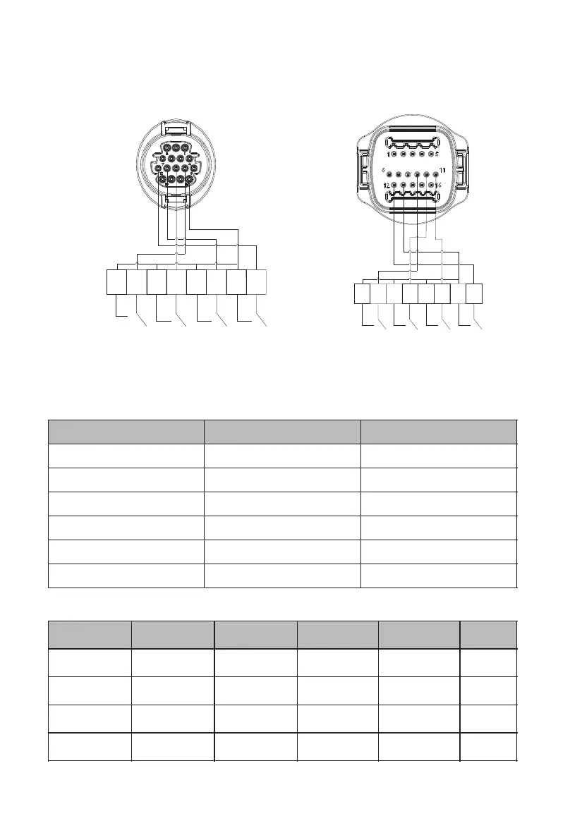
6.4.1.1 The following table describes the connector pin assignment and function:
6.4.1.2 The inverter is preconfigured to the following RRCR power levels:
WARNING
25
26
6.4.1 Using the Power Control Interface for EU
Fig 6.9 Inverter – RRCR Connection
DRM socket1
1 2 3 4 5 6 7 8
K1 K2 K3 K4
1 2
3
4 5 6 7 8
K1
K2
K3
K4
DRM socket2
Bekijk gratis de handleiding van Growatt MAX 185-253KTL3-X HV, stel vragen en lees de antwoorden op veelvoorkomende problemen, of gebruik onze assistent om sneller informatie in de handleiding te vinden of uitleg te krijgen over specifieke functies.
Productinformatie
| Merk | Growatt |
| Model | MAX 185-253KTL3-X HV |
| Categorie | Niet gecategoriseerd |
| Taal | Nederlands |
| Grootte | 11687 MB |


