Growatt MAX 185-253KTL3-X HV handleiding
Handleiding
Je bekijkt pagina 27 van 77
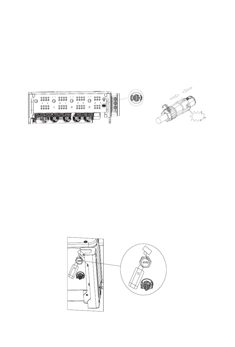
Fig 6.8A
23
24
Fig 6.8B
The MAX 175-253KTL3-X HV series inverters are equipped with a USB interface as
standard, which can be connected to a USB to WIFI module, Shine GPRS-X2, Shine WIFI-
X, Shine 4G-X, Shine Link-X and other optional monitoring modules to realize remote
Monitoring function. In addition, you can also quickly upgrade the inverter software
through the U disk:
Steps to install the monitoring module:
1> Loosen the waterproof cover of the USB interface and remove it.
2> As shown in Figure 6.8A, insert the Shine GPRS-X2 module into the USB interface,
and the LED of the Shine GPRS-X2 module will be on.
3> As shown in Figure 6.8B, make sure that the △ is facing upwards, insert the
monitoring module into the USB interface, and tighten the lock.
Note: If you use a USB to WIFI module, when the operator leaves, please take the module
and the data cable away, and tighten the waterproof cover to prevent water from
entering the interface.
The Inverter Side
The Inverter Side
The Inverter Side
The Inverter Side
up
Installation
Remove
6.4 Inverter demand response modes (DRMS)
This series inverter has the function of demand response modes, We use 16-Pin socket as
inverter DRMS connection.
DRMS application description
Ø Applicable to Commission Regulation (EU) 2016/631.
Ø DRM0, DRM5, DRM6, DRM7, DRM8 are available.
Damage to the inverter due to moisture and dust penetration
Ø Make sure the cable gland has been tightened firmly.
Ø If the cable gland are not mounted properly, the inverter can be
destroyed due to moisture and dust penetration. All the warranty
claim will be invalid.
Excessive voltage can damage the inverter!
External voltage of DRM PORT don't over +5V.
Information
CAUTION
WARNING
6.3.2 USB port
In MAX 175-253KTL3-X HV series inverters, RS485 interface is standard. The connection
steps of RS485 communication line are as follows:
1) Unscrew the waterproof cover of the COM interface and remove it.
2) Connect the RS485 communication line to the port of 485-1.
3) The inverter is connected hand in hand through the RS485 communication line, and
the end of the communication line 485_A/B is connected to the monitoring equipment to
realize multi-machine remote monitoring.
Note: When locking the RS485 cable screw, the torque is 4kgf·cm.
Fig 6.7
Click!
Bekijk gratis de handleiding van Growatt MAX 185-253KTL3-X HV, stel vragen en lees de antwoorden op veelvoorkomende problemen, of gebruik onze assistent om sneller informatie in de handleiding te vinden of uitleg te krijgen over specifieke functies.
Productinformatie
| Merk | Growatt |
| Model | MAX 185-253KTL3-X HV |
| Categorie | Niet gecategoriseerd |
| Taal | Nederlands |
| Grootte | 11687 MB |


