Gree GMVGMS-GW12 handleiding
Handleiding
Je bekijkt pagina 6 van 19
UM Version 1.1 6 GMVGMSGW 1/12
3. System Layout and Connectivity
The following sub-sections provide details on the different connectivity options of the system
and how to use the various functions of the GMS GW.
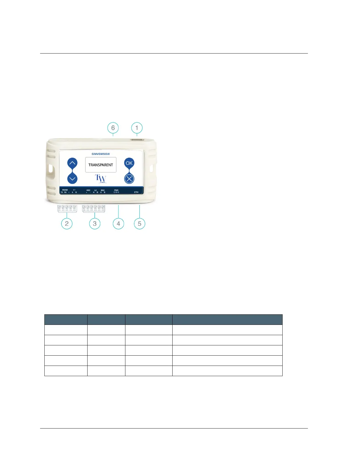
3.1 Device Layout and Connectivity
(1) Mi
ni USB Device Connector
(2) RS-485 Line 1 Connector
(3) RS-485 Line 2, Power Connector
(4) PWR
(5) ETH Connector
(6) LCD Screen
Figure 1 – Device Layout
3.1.1 Mini USB Device Connector
Used to connect the GMS GW to the PC USB Host for firmware updates and maintenance
operations.
3.1.2 RS-485 Line 1 Connector
RS232/IO Pin Pin Name Signal Level Function Description
1 RS232_TX Not in Use (Future)
2 RS232_RX Not in Use (Future)
3 VDC- GND Ground
4 L1 A RS-485 Gree split line 1, A terminal
5 L1 B RS-485 Gree split line 1, B terminal
Table 3 – RS-485 L1 Connector
Bekijk gratis de handleiding van Gree GMVGMS-GW12, stel vragen en lees de antwoorden op veelvoorkomende problemen, of gebruik onze assistent om sneller informatie in de handleiding te vinden of uitleg te krijgen over specifieke functies.
Productinformatie
| Merk | Gree |
| Model | GMVGMS-GW12 |
| Categorie | Niet gecategoriseerd |
| Taal | Nederlands |
| Grootte | 2433 MB |

