Gossen Metrawatt METRALINE ENERGY U282A handleiding
Handleiding
Je bekijkt pagina 2 van 2
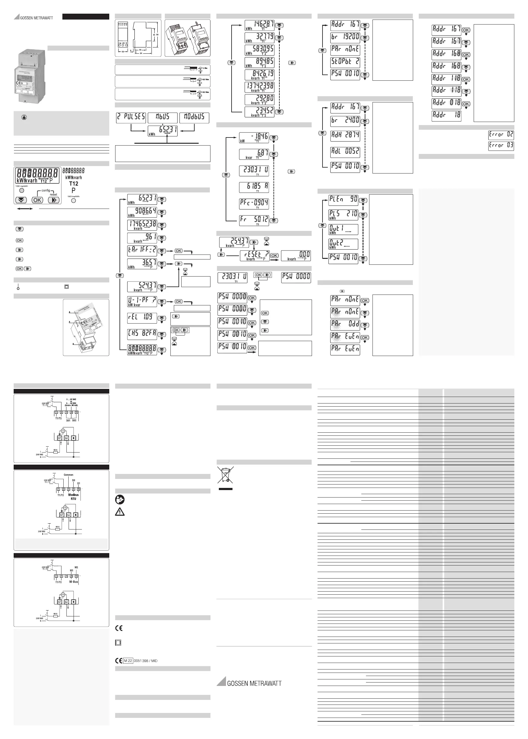
Symbols
• Measuring elements
• Protected by double insulation
Sealable terminal covers
Dimension
A) Device code and certification data indications
B) Safety-sealing between upper and lower
housing part
MID calibrated
Ordering information
Model Communication
U282A S0 Pulse outputs MID certified
U282B Built in RS-485 Modbus RTU MID certified
U282C Built in M-Bus (1 unit Load) MID certified
(
*
) For swiss market only active energy on display
Operating instructions
• This family of metering equipments provides the essential
measurement capabilities required to monitor a single phase
electrical installation.
• There are 3 models, mainly distinguished by the type of remote
communication:
(
*
) certification parameters: 0.25-5 (80) A, Class B, 230 VAC 50 Hz,
-25 °C ... +55 °C, 4 Quadrants, 2 Tariffs.
• Active Energy Class B (according to EN-50470)
and Reactive Energy Class 2 (according to IEC 62053-23)
• Direct connected (up to 80 A)
• Backlightet
LCD display and 3 push-button keys (to read
Energies, V, I, PF, F, P, Q and to configure some parameters)
• Display with 8 digits.
• Self supplied (by the input voltage itself)
• 2 DIN modules width (36 mm)
• 2 Tariffs controlled by a 230 VAC digital input
• Depending on the models:
- 2 S0 standard low voltage pulse outputs, or
- communication via Modbus RTU or
- communication via M-Bus (1 unit load)
80 A direct connection main terminals
Screw driver PZ2
Cable stripping length and terminal screw torque
Tariff and Pulse outputs terminals
Screw driver blade 0.8x3.5 mm
Communication terminals
Screw driver blade 0.8x3.5 mm
RISK OF ELECTRIC SHOCK, BURNS OR EXPLOSION
This device must be installed and maintained ONLY by qualified
and duly authorized personnel.
During its installation, be sure there is no voltage applied
.
• Running tarif, called tarif
• kWh / kvarh display
• Precision control LED
Display
• Energy value
• Energy export (received )
• Energy import (delivered )
•
OK key: This key is used alone to enable a new menu function or to confirm
a parameter value during its modification. Its pushing is accepted only if
shorter than 1.5 seconds
•
Scroll Key: This key is used to scroll pages and to modify parameters value.
Its pushing is accepted only if it is shorter than 1.5 second.
Commands
•
ESC key: This key is used alone to exit from a sub-menu, to cancel a
parameter modification or to go back to the main page. In these cases, its
pushing is accepted only <1.5 seconds
• Energy value “Partial”
•
A long pushing (>1.5 seconds) of the “ESC key” is used in the Partial Energy
Registers Pages to reset their values.
•
Push these 2 keys together, for at least 1.5 seconds, to enter
into the Configuration Menu
Device Switch-on and Main Page
U282A U282C U282B
• Energy import (supplied ) • Energy export (absorbed )
Display Back light
• If no button is pushed for 40 seconds, the display goes back to the Main Page and the
backlight is switched off.
• The first button pushing does not change the page but is used to switch the backlight on.
Main Page:
This page appears not only at device switch on, but also in case for 30 seconds no key is
pushed. The value is the sum of 2 registers:
Imported Act. Energy Tariff T1 + Imported Act. Energy Tariff T2. (or, alternatively, the sum
of the Exported ones).
Main Menu
Main Menu
Tariff 1-2 Energy Registers List
> 1.5 sec.
> 1.5 sec.
Access to the
Configuration Menu
Shortly
Partial Energy
Register Reset
Procedure
Instantaneous Measures list
Tariff 1-2 Energy Registers List
Main Menu
Instantaneous Measurements List
Watt
var
V
A
PF
Hz
PFc = Capacitive
PFi = Inductive
Shortly
Main Menu
Shortly
Partial Energy Registers Reset Procedure
> = 1.5 sec.
1.5 sec. for Partial Registers
Shortly
Access to the Configuration Menu
> 1.5 sec.
Confirm the Digit
Increase the Digit
Main Menu
Default Password = 0010
Password Correct
Parameters Menu
Parameters Available in U282B
Modbus Address: 1 ... 247
Baud Rate
1200-2400-4800-9600
19200-38400
Parity: None-Even and Odd
Stop Bits: 1/2
Password: 0000 ... 9999
Parameters Available in U282C
M-Bus Primary Address: 0 ... 250
Baud Rate
300-600-1200-2400
4800-9600
M-Bus Secondary Addresse
(4 MS digits)
M-Bus Secondary Addresse
(4 LS digits)
Password: 0000 ... 9999
Diagnostic Message
Parameters Available in
U282A
S0 p/kWh: 1 ... 1000
Pulse length (ON time)
30 ... 100 msec
S01 Pulse Output Mode
kWh,
kWh,
kvarh,
kvarh,
kWh T1,
kWh T2,
S02 Pulse Output Mode
Password: 0000 ... 9999
Multivalue Parameters Modification
Start
Change
Change
Confirm (End)
In this example the Parity value is changed from None to Even. In any
moment, push the “” key to stop the modification
Numeric Parameters Modification
Start
7
8
Confirm
6
7
8
9
0
1
Confirm
In this example the Address value is modified from 167 to 18.
1
2
3
4
5
6
7
8
9
0
Confirm
Error Condition
If the display shows these messages, the meters has got a
malfunction and must be replaced.
Service and Maintenance
It should not be necessary to recalibrate device during its lifetime as it is an electronic meter with
no moving parts with electronics and voltage and current sensors that do not naturally degrade or
change with time under specified environmental conditions. If a degradation in the performance is
observed the device has probably been partly damaged and should be sent for repair or exchanged.
If the meter is dirty and needs to be cleaned, use lightly moistened tissue with a water based mild
detergent. Make sure no liquid goes into the meter as this could damage the meter.
3-447-130-15
METRALINE I ENERGY
Single-phase Digital Energy meters
Direct connection 80 A
ENGLISH
IIST322-01 - 1/10.22
Wiring diagram
Model
M-Bus
Model
Modbus
Model
S0
Technical Data
Data in compliance with EN 50470-1, EN 50470-3, EN 62053-23 and EN 62053-31
Direct Connection
80 A
Direct Connection
80 A
built-in
Pulse output
S0
Comm
.
Modbus/M-Bus
General characteristics
•
Housing
DIN 43880 DIN 2 Modules 2 Modules
•
Mounting
EN 60715 35 mm DIN rail DIN rail
•
Depth
mm 70 70
•
Weight
g 175 175
Operating features
•
Connection to single-phase network
n° wires 22
•
Storage of energy values and config. Internal flash memory
- yes yes
•
Tariff for active and reactive energy
n° 2 T1 / T2 T1 / T2
Approval (according to EN 50470-1, EN 50470-3)
•
Reference Voltage Un
VAC
230 230
•
Reference Current (Iref)
A 55
•
Minimum Current (Imin)
A 0.25 0.25
•
Maximum Current (Imax)
A 80 80
•
Starting Current (Ist)
A 0.015 0.015
•
Reference Frequency (fn)
Hz 50 50
•
Number of phases (number of wires)
-
1 (2) 1 (2)
•
Certified Measures
kWh kWh T1, kWh T1 kWh T1, kWh T1
kWh T2, kWh T2 kWh T2, kWh T2
•Accuracy
Active Energies (accor. to EN 50470-3) and Active Powers
classe
B B
Reactive Energies (accor. to EN 62053-23) and Reactive Power
classe
2 2
Supply Voltage and Power Consumption
•
Operating Supply Voltage range
V 92 ... 276 92 ... 276
•
Maximum Power Dissipation (Voltage circuit)
VA (W)
⩽
2 (1)
⩽
2 (1)
•
Maximum VA burden (Current circuit) @ Imax
VA
⩽
1
⩽
1
•
Voltage Input Waveform
- AC AC
• Voltage impedance MΩ 11
• Current impedance mΩ ⩽20 ⩽20
Overload capability
•
Voltage
continuous VAC
276 276
Temporary (1 s) VAC
300 300
•
Current
continuous
A 80 80
Temporary (10 ms)
A 2400 2400
Measuring Features
•
Voltage range VAC
92 ... 276 92 ... 276
•
Current range
A 0.015 ... 80 0.015 ... 80
•
Frequency range
Hz
45 ... 65 45 ... 65
•
Measured Quantities - V, A, kWh, kVARh, V, A, kWh, kVARh,
PF, Hz, kW, kVAR PF, Hz, kW, kVAR
Display features
•
Display type
LCD backlightet
- 6.2 +3 6.2 +3
Energy digits dimension
mm 6 x 3 6 x 3
•
Active Energy
6
digits
+ 2
decimal digits
min. ... max. kWh 0.01 ... 999999.99 0.01 ... 999999.99
•
Reactive Energy
6
digits
+ 2
decimal digits
min. ... max. kvarh 0.01 ... 999999.99 0.01 ... 999999.99
• Voltage 3 digits
+ 2
decimal digits V 92.00 ... 276.00 92.00 ... 276.00
• Current 2 digits
+ 2
decimal digits A 0.00 ... 80.00 0.00 ... 80.00
• Power factor 1 digits
+ 3
dec. digits + capac./induc. indic. - 0.000 ... 1.000 0.000 ... 1.000
• Frequency 2 digits
+ 2
decimal digits Hz 45.00 ... 65.00 45.00 ... 65.00
• Active Power 2 digits
+ 2
ecimal digits with sign kW 0.00 ... 17.40 0.00 ... 17.40
• Reactive Power 2 digits
+ 2
ecimal digits with sign kVAR 0.00 ... 17.40 0.00 ... 17.40
•
Running Tariff
1
digit
- T1 / T2 T1 / T2
•
Display refresh period
s 11
Optical metrological LED
•
Front mounted red LED (meter constant)
proportional to active imp/exp Energy
p/kWh 1000 1000
Safety
•
Protective class
classe II II
•
AC voltage test (EN 50470-3, 7.2)
kV 44
•
Degree of pollution
- 22
•
Operational voltage
V 300 300
•
Impulse voltage test
1.2/50 μs-kV 66
•
Housing material flame resistance
UL 94 classe V0 V0
•
Safety-sealing between upper and lower housing part -
yes yes
Pulse Outputs (S0 signals, acc. to IEC 62053-31)
• Pulse Ouput 1 or 2 selectable -
kWh , kWh
kvarh , kvarh
-
kWh (T1) , kWh (T2)
•
Pulse Rate adjustable
p/kWh - p/kvarh
1 ... 1000 -
•
Pulse ON duration adjustable
msec
30 ... 100 -
•
Operating voltage
Min. - Max. VAC (DC)
5 ... 28 (5 ... 39) -
•
Pulse ON maximum current in the range
3 ... 28 VAC (5 ... 39 VDC) mA 90 -
•
Pulse OFF leakage current
in the range
3 ... 28 VAC (5 ... 39 VDC) μA 1
-
• Isolation class - SELV -
Tariff
• Tariff 1 - open contact open contact
• Tariff 2 VAC 230 ±20% 230 ±20%
•
Input impedance
kΩ 224 224
Embedded communication
• Modbus RTU RS-485 - 3
wires
- -
baud rate min.-max. 1200-38400 bps
• M-Bus 2
wires
- -
baud rate min.-max. 300-9600 bps
• Isolation class - -SELV
IR Connectable Communication Modules
•
For communication moduls connection
(LAN-TCP/IP / M-Bus / Modbus RTU / KNX) - yes yes
Connection terminals
•
Screwdriver for mains terminals
head with Z +/-
POZIDRIV PZ2 PZ2
•
Screwdriver for tariff and communic. terminals
slotted head
mm 0.8 x 3.5 0.8 x 3.5
•
Terminal capacity main current paths solid wire min. (max)
mm
2
1.65 (33) 1.65 (33)
stranded wire with sleeve min. (max)
mm
2
1.65 (33) 1.65 (33)
•
Terminal capacity for tariff and communication solid wire min. (max)
mm
2
1 (4) 1 (4)
stranded wire with sleeve min. (max)
mm
2
1 (2.5) 1 (2.5)
Environmental conditions (storage)
•
Temperature range
°C -25 ... +70 -25 ... +70
Environmental conditions (operating)
•
Temperature range
°C -25 ... +55 -25 ... +55
•
Mechanical environment
- M1 M1
•
Electromagnetic environment
- E2 E2
•
Installation Indoor
- yes yes
•
Altitude
(max)
m ⩽
2000
⩽
2000
•
Humidity yearly average, not condensing
-
⩽
75%
⩽
75%
on 30 days per year (not condensing)
-
⩽
95%
⩽
95%
•
IP rating
- IP51(
*
)/IP40 IP51(
*
)/IP40
(*) The metering equipment must be installed inside a cabinet with IP rating IP51 or better.
RT = termination resistance (apply RT in cases reccomended by RS-485 norm)
Please read this important information!
Intended Use / Use for Intended Purpose
The instrument is a digital multifunctional energy meter certified in accordance with
MID. Integrated 4-quadrant measurement permits measurement of energy import and
export.
Thanks to MID certification, acquired data (display) can also be used for the purpose
of billing energy costs to third parties.
Via integrated communication interfaces, the values are also forwarded to superordi-
nate management systems. Protection against tampering is provided through ade-
quate measures (tamper-proof cover).
Safety of the operator, as well as that of the instrument, is only assured when it’s used
for its intended purpose
Use for Other than Intended Purpose
Using the instrument for any purposes other than those described in the product do-
cumentation is contrary to use for intended purpose.
Liability and Guarantee
Gossen Metrawatt GmbH assumes no liability for property damage, personal injury or
consequential damage resulting from improper or incorrect use of the product, in par-
ticular due to failure to observe the product documentation. Furthermore, all guaran-
tee claims are rendered null and void in such cases.
Nor does Gossen Metrawatt GmbH accept any liability for data loss.
1 instrument ( (U282A) - (U282B) - (U282C) )
1 operating instructions
Read and follow these instructions carefully and completely in order to en-
sure safe and proper use. Keep for future reference.
DANGER
Electric shock due to live components!
Life endangering due to electric arcs!
Touching voltage conducting components is life endangering!
– The installation and any work performed on the instrument may only be carried out
by a qualified electrician.
– Observe and comply with all safety regulations which are applicable for your work
environment.
– Wear suitable and appropriate personal protective equipment (PPE) whenever wor-
king with the instrument.
– During installation, the installation environment must be voltage-free. For that, ob-
serve the five safety rules in accordance with DIN VDE 0105-100.
ATTENTION
Faulty installation & incorrect operation
Faulty installation/incorrect operation can damage your instrument/system.
Risk of malfunctions and disruptions
– Comply with the specified technical data and conditions
– Do not install the instrument in potentially explosive atmospheres.
– Do not install the instrument in locations where it may be exposed to direct sun-
light.
– Install and operate the instrument only if it and all connection cables and leads are
in good working order and damage-free. Inspect the instrument at regular intervals.
– If the instrument doesn’t function flawlessly, permanently remove it from operation
and secure it against inadvertent use.
European conformity marking
Double insulation (protection category II)
CE and metrology mark with indication of year (M22) and registration number of the
notified body for module D, country-specific calibration validity period
– DIN 43880
– EN 50470-1
– EN 50470-3
– EN 60715
– EN 62053-31
– IEC 62053-23
Transport and store the instrument only within the limits of permissible ambient con-
ditions. Also use suitable packaging in order to ensure adequate protection against en-
vironmental influences and mechanical stress.
The instrument is maintenance-free. Keep outside surfaces clean.
Clean the instrument only with a dry cloth.
Applications
Scope of Delivery
Safety Instructions
Symbols on the Instrument
Standards, Regulations and Directives
Transport & Storage
Maintenance
Comply with national recalibration regulations and laws. The calibration period in Ger-
many is 8 years.
A broken manufacturer’s seal means equals invalidated calibration. The instrument
must not be used for billing purposes.
If your instrument requires repair, please contact our service department; see Support
& Contact.
Unauthorized modification of the instrument is prohibited. This also includes opening
the meter.
If it can be ascertained that the instrument has been opened by unauthorized per-
sonnel, no guarantee claims can be honored by the manufacturer with regard to per-
sonal safety, measuring accuracy, compliance with applicable safety measures or any
consequential damages. If the manufacturer’s seal is damaged or removed, all gua-
rantee claims are rendered null and void.
The instruments are guaranteed for a period of 2 years after shipment. The manu-
facturer’s guarantee covers materials and workmanship. Damage resulting from use
for any other than the intended purpose or operating errors, as well as any and all con
sequential damage, are excluded.
• The following comments refer specifically to the legal situation in
the Federal Republic of Germany. Owners or end users who are
subject to other national requirements are required to comply with
the respectively applicable national requirements and to imple-
ment them correctly on site
• The symbol on the left depicting a crossed-out garbage can on
wheels refers to the legal obligation of the owner or end user (Ger-
man electrical and electronic equipment act ElektroG and German
battery act BattG) not to dispose of used electrical equipment and
batteries with unsorted municipal waste (“household trash”).
• Old devices, electrical or electronic accessories and waste batte-
ries (including rechargeable batteries) used in Germany can be
returned free of charge to Gossen Metrawatt GmbH or the service
provider responsible for their disposal. Further information can be
found on our website.
Recalibration
Repairs & Manufacturer’s Guarantee
Disposal & Environmental Protection
Support and Contact
Please contact us at
+49 911 8602-0
Monday – Thursday: 08:00 Uhr – 16:00 Uhr
Friday: 08:00 Uhr – 14:00 Uhr
support.industrie@gossenmetrawatt.com
Please contact GMC-I Service GmbH for repairs, replacement parts and calibration:
+49 911 817718-0
service@gossenmetrawatt.com
www.gmci-service.com
CE Declaration
The device fulfills all requirements of applicable EU directives and national regulations.
We confirm this with the CE mark.
The CE declaration is available on our website:
https://www.gmc-instruments.de/en/services/download-center/download-center/
Gossen Metrawatt GmbH
Südwestpark 15 • 90449 Nürnberg • Germany
Phone +49 911 8602-0 • Fax +49 911 8602-669
E-mail info@gossenmetrawatt.com • www.gossenmetrawatt.com
© Gossen Metrawatt GmbH
• Prepared in Germany
• Subject to change, errors excepted
• PDF version available on the Internet.
All trademarks, registered trademarks, logos, product names and company names are the
property of their respective owners.
Bekijk gratis de handleiding van Gossen Metrawatt METRALINE ENERGY U282A, stel vragen en lees de antwoorden op veelvoorkomende problemen, of gebruik onze assistent om sneller informatie in de handleiding te vinden of uitleg te krijgen over specifieke functies.
Productinformatie
| Merk | Gossen Metrawatt |
| Model | METRALINE ENERGY U282A |
| Categorie | Niet gecategoriseerd |
| Taal | Nederlands |
| Grootte | 1663 MB |


