Giles GHM-6C handleiding
Handleiding
Je bekijkt pagina 21 van 57
11
Unit must be adequately & properly grounded. Improper grounding can create a potential electri
cal shock hazard for operating personnel & customers. Always refer to local electrical code to ensure that this
appliance and all other electrical equipment are in compliance with grounding requirements.
Consult a professional electrician, or qualified kitchen equipment service technician, to ensure that circuit
breakers & wiring are of sufficient rating to power the appliance load.
The GHM Merchandiser is available for the various electrical specifications listed below. Check the rating label on the
rear of the unit to determine correct power supply. A wiring diagram has been provided with this appliance to aid with
installation ... please verify that it actually corresponds to the unit being installed.
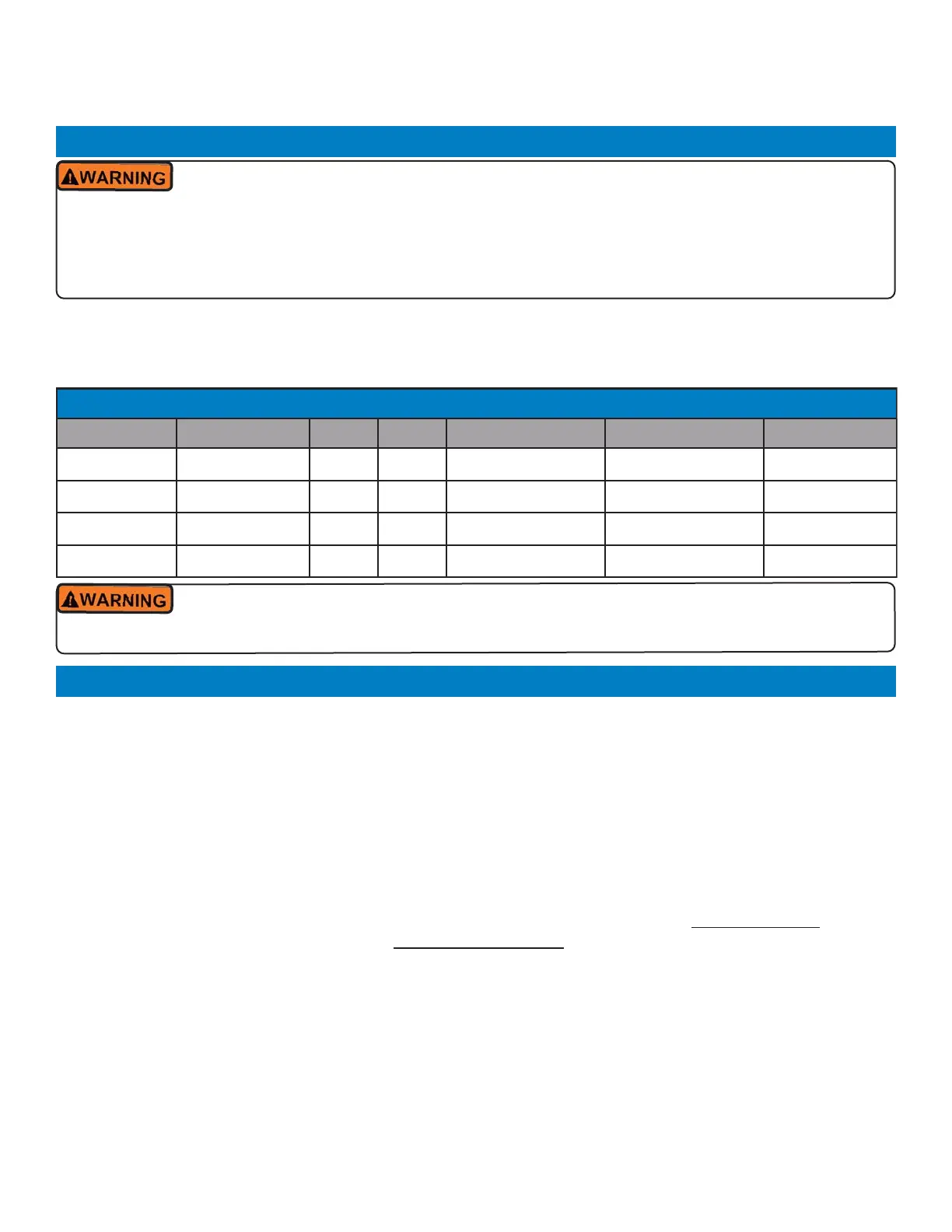
Table 2.05, Electrical Requirements
Model Voltage Phase Hz kW Amps Breaker
GHM4 208 / 240 1 60 2.7 / 3.2 13.3 20
GHM5 208 / 240 1 60 3.7 / 4.3 17.9 25
GHM6 208 / 240 1 60 4.7 / 5.4 22.4 30
GHM8 208 / 240 1 60 6.6 / 7.6 31.6 40
1. Verify installation of appropriate circuit breakers in the main electrical panel, see Table 2.05. above.
2. Connect appropriately sized power supply wiring to breaker & route to unit, providing enough length to allow unit to
be moved as needed for cleaning or service ... generally, either 10/3 SO cord or 10‐ga. wire in conduit is acceptable.
3. On the attendantside, remove retaining screws & carefully lower the hinged control panel, see Section 2.06.1, Elec‐
trical Diagram ... if installing a GHM‐8, only the righthand panel section needs to be opened.
Be careful not to intangle the small copper capillary tubes of the thermostat controls.
4. Install the provided cable strain relief connector (for SO cord), or customer‐provided conduit fittings in hole on bot
tom panel. Feed sufficient wire for connection through the strain relief or conduit.
5. Securely connect incoming power & ground wires to terminal blocks [L1] [L2] [G], see Section 2.06.1, Electrical Con‐
nection Diagram. NOTE: There are two (2) terminal blocks marked [L2] connected by a red plug‐in jumper
... con
nect incoming power at [L1] & middle [L2] ... DO NOT remove jumper
.
6. Before closing control panel, verify that fuses are properly installed in fuse holders. Carefully close the panel, taking
care not to pinch wiring. Reinstall retaining screws & tighten securely.
7. Ensure that appliance POWER switch is [OFF] ... turn ON circuit breaker in electrical panel supplying power to the
appliance ... place power switch in to [ON]. LED lighting will illuminate & control panel cooling fan will start.
8. Variable heat controls for each well are located across the rear control panel, see Section 2.06.1. Rotate all of the
top & bottom heat control knobs clockwise to the full [ON] position. Confirm that the red indicator lights on each
panel illuminate, and that all sections of the pan bottom and all of the top ceramic heaters begin to heat, then return
all controls to [OFF].
2.05 Electrical Requirement
2.06 Electrical Connection
Before continuing with installation, be certain that power supply to the unit is disconnected &
locked out.
Installation
Heated Merchandiser
GHM-LED Series
Bekijk gratis de handleiding van Giles GHM-6C, stel vragen en lees de antwoorden op veelvoorkomende problemen, of gebruik onze assistent om sneller informatie in de handleiding te vinden of uitleg te krijgen over specifieke functies.
Productinformatie
| Merk | Giles |
| Model | GHM-6C |
| Categorie | Niet gecategoriseerd |
| Taal | Nederlands |
| Grootte | 11742 MB |

