Furuno AR-100M handleiding
Handleiding
Je bekijkt pagina 18 van 122
1. OPERATION
1-4
3 Working indicator Rotates clockwise when the system is working correctly. Stops rotat-
ing when the system is frozen or malfunctioning.
4 Time and date Displays the current time and date. You can select the time to use, lo-
cal or UTC. See section 1.11.
5 Error button Opens/closes the error frame. This button appears only when a minor
error occurs. Click the button to open the error frame, then confirm the
error message.
6 Main menu The main menu contains customizing options for this equipment. To
open/close the menu, click the menu button. You can also close the
main menu by clicking the video image.
7 Range Shows the current display range in use for the AR navigation system.
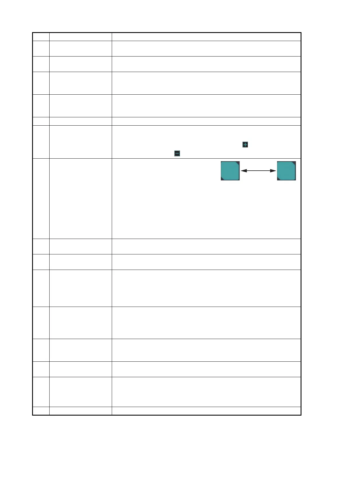
8 Range control button Adjusts the display range in use for the AR navigation system. The
symbols on the AR navigation screen and TVI (Top View Indicator)
change according to the display range. Click the button to increase
the range, or click the button to reduce the range.
9 TVI Presentation
mode button
Toggles between head-up and north-
up presentation modes for the TVI.
The indication on the button changes
according to the presentation mode.
• [H-UP] (Head Up): Displays the symbols with the heading line of
own ship at the top of the TVI. The heading line and the direction of
the field of view are fixed, and the symbols rotate according to the
heading.
• [N-UP] (North Up): True north (0
°) is at the top of the TVI. The head-
ing line and the direction of the field of view rotate according to the
heading.
10 TVI (Top View Indica-
tor)
Displays the TT and AIS target’s location in a circle about own ship.
For details, see section 1.5.
11 Azimuth scale Provides an estimate of the bearing to a target. You can move the az-
imuth scale vertically by the drag and drop operation.
12 Bearing line A maximum of two vertical guide lines (dashed lines) can be entered
at any bearing position. Click the bearing line marker () on the azi-
muth scale to show/hide the bearing line. Drag and drop the bearing
line to move the line. You can also move the bearing guide by clicking
anywhere on the upper side of the azimuth scale.
13 Heading guide You can estimate the heading of own ship, by reading the point at
which the heading guide intersects the azimuth scale.
Note: When the IP camera position is offset from the ship’s center, the
heading guide is not aligned with the ship’s bow on the video image.
14 Horizon line Indicates the horizon, and is used to adjust the video image position.
Normally, hide the horizon line. For how to show/hide the horizon line,
see subsection 1.8.3.
15 Waypoint information Display the information (course to the next waypoint, time to go, dis-
tance) for the To waypoint on the route.
16 No-go area Indicates the area where the vessel is not allowed to go. You can
show or hide the visible wall for the no-go area. See subsection 1.9.4.
When you hide the visible wall, the no-go area is drawn only with a
line.
17 User chart label Indicates the user chart input from ECDIS.
No. Name Description
H-UP N-UP
Click
Bekijk gratis de handleiding van Furuno AR-100M, stel vragen en lees de antwoorden op veelvoorkomende problemen, of gebruik onze assistent om sneller informatie in de handleiding te vinden of uitleg te krijgen over specifieke functies.
Productinformatie
| Merk | Furuno |
| Model | AR-100M |
| Categorie | Niet gecategoriseerd |
| Taal | Nederlands |
| Grootte | 28951 MB |


