Handleiding
Je bekijkt pagina 16 van 26
En-15
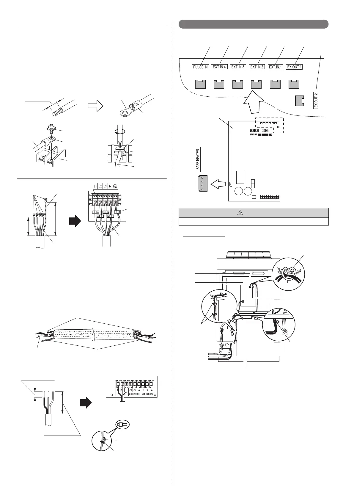
(1) Connecting the power supply cable
Caution when wiring cable
1) Use ring terminals with insulating sleeves as shown in the fi gure to connect to
the terminal block.
2) Securely clamp the ring terminals to the cables using an appropriate tool so that
the cables do not come loose.
3) Use the specifi ed cables, connect them securely, and fasten them so that there is
no stress placed on the terminals.
4) Use an appropriate screwdriver to tighten the terminal screws. Do not use a
screwdriver that is too small, otherwise, the screw heads may be damaged and
prevent the screws from being properly tightened.
5) Do not tighten the terminal screws too much, otherwise, the screws may break.
6) See the table for the terminal screw tightening torques.
Strip 10 mm
Cable
Screw with
special washer
Ring terminal
Terminal block
Ring terminal
Sleeve
Screw with
special washer
Ring terminal
Cable
Ring terminal: M8
Earth (Ground)
cable
Cable clamp
Blue wire
Power supply Terminal
Connect the blue wire
to the “N” terminal.
70 to 80 mm
90 to 100 mm
* Use a ring terminal to connect the electric cables to the power supply terminal
board.
(2) Connecting the transmission cable
Sealing transmission cable
Connect both ends of the sealed wires of the transmission cable to the earth terminal
of the equipment or to the earth screw near the terminal.
Be very careful that the screws are not overly tightened as the wires may snap and
the terminal may be damaged.
Wind with insulation tape to
prevent short circuit
Use one side of the
twisted-pair cable
Connect both ends of sealed
cable to earth.
Be sure to use one side of a twisted-pair cable when using transmission cable with 2
sets of twisted-pair cables.
RB
IN
Cable clip
Cable tie
(Accessory)
40 mm or more
8 to 10 mm
6. 7. External input and external output
6. 7. 1. Terminal position
Input 5
CN135
(ORANGE)
Outdoor unit PC board
CN131
(YELLOW)
CN136
(BLACK)
CN137
(BLUE)
CN134
(RED)
CN115
(BLACK)
CN133
(WHITE)
CN132
(GREEN)
Input 4 Input 3 Input 2 Input 1 Output 1
Output 2
CAUTION
Do not bundle the cable for base heater with other cables.
(Example)
In case of Outdoor unit
(1) Insert the connector to CN134 (Red) and CN135 (Orange) of control PC board.
(2) Fix it to the wire with the attached cable tie.
Clamp
CN134
(Red)
CN115
(Black)
Cable tie
(Accessory)
Wire
Clamp
CN135
(Orange)
▪ Do not clamp the base heater cable.
6. 7. 2. External input terminal
• Setting to low noise mode, outdoor unit operation peak control setting, emergency/
batch stop and electricity meter pulse are possible from the outside.
• Except for wattmeter pulse reception (CN135) among external input terminals, only
the Master unit is eff ective.
Wiring method and specifi cations
* A twisted pair cable (0.33 mm
2
(22AWG)) should be used. Maximum length of
cable is 150 m.
* Use an external input and output cable with appropriate external dimension, de-
pending on the number of cables to be installed
* For each input, pin No.1 is of positive polarity and pin No.2 is of ground level.
9378945623-02_IM_EN.indd 159378945623-02_IM_EN.indd 15 2022/10/28 8:43:19 AM2022/10/28 8:43:19 AM
Bekijk gratis de handleiding van Fujitsu AJH090LNTCH, stel vragen en lees de antwoorden op veelvoorkomende problemen, of gebruik onze assistent om sneller informatie in de handleiding te vinden of uitleg te krijgen over specifieke functies.
Productinformatie
| Merk | Fujitsu |
| Model | AJH090LNTCH |
| Categorie | Airco |
| Taal | Nederlands |
| Grootte | 5465 MB |


