Handleiding
Je bekijkt pagina 6 van 24
En-6
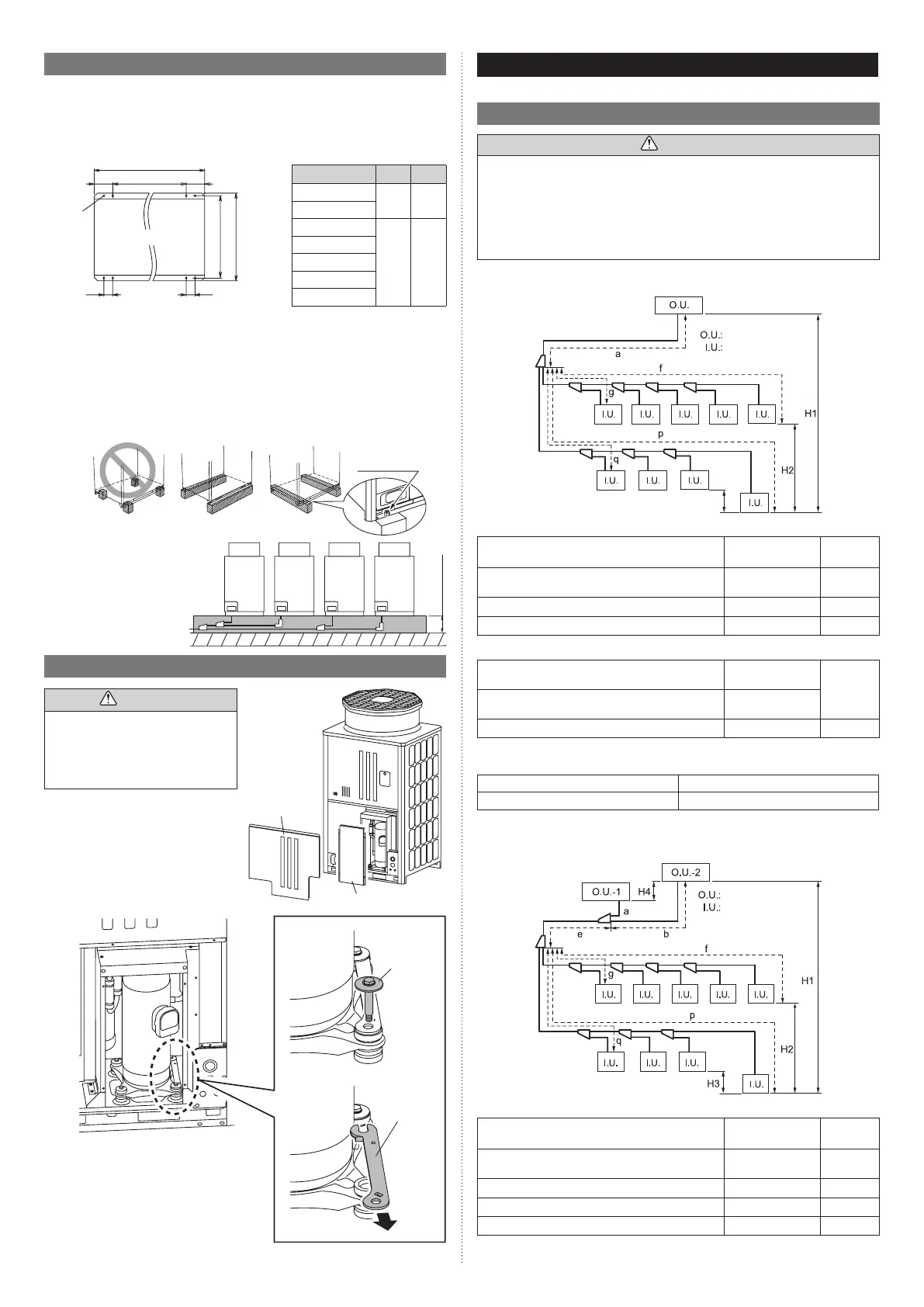
3.5. Installing the unit
• Install the unit level. (within 0.3 degrees).
• Install 4 or more anchor bolts at the 8 locations indicated by arrows (Fig. A).
• Place the left and right anchor bolts at a distance further away than the dimensions of A
in the Table A.
(Excludingthecasewhereanchorboltsareinstalledat8places.)
Fig. A
732
765
78
160
78
A
B
160
Holes:
15×17
(8 places)
Bottom view
(Unit: mm)
Table. A
Model A B
AJG072JATAH
610 930
AJG090JATAH
AJG108JATAH
920 1240
AJG126JATAH
AJG144JATAH
AJG162JATAH
AJG180JATAH
• To minimize vibration, do not install the outdoor unit directly on the ground.
Instead, install it on top of a firm platform (such as concrete block). (Fig. B)
• The foundation base should be able to support the product and the foot width of the
product should be more than 46.5 mm.
• Depending on the installation condition, vibration during the operation of the unit may
cause noise and vibration.
Install vibration-proofing materials (such as rubber pads).
• Consider the removal space of the connection piping when installing the foundation.
• Secure the equipment firmly with anchor bolts, washers, and nuts.
Fig. B
Bolt (M10)
*Do not use a four-corner support foundation.
GOODPROHIBITED GOOD
Fig. C
When installing piping from
the bottom of the outdoor
units, the required space
undertheoutdoorunit≥200
mm.
* Install the branch kit hori-
zontally.
200 mm
or more
3.6. Removing the compressor xture
Service panel
(bottom)
Compressorboxcover
CAUTION
Be sure to remove the compressor
fixture.Failuretodosomaycausethe
outdoor unit to vibrate.
Donotdiscardtheremovedfixtureasit
will be used as a valve wrench. (Refer to
“8. PIPE INSTALLATION II”)
(1) Remove the service panel (bottom)
andthecompressorboxcover.
(2)
(3)
(2) Removethecompressorfixingboltonthe
front right side.
(3) Pulloutthecompressorfixturetowardyou.
(4) Reinstallthefixingboltremovedin(2)and
tighten.
(5) Reinstallthecompressorboxcover
removed in (1).
(6) If piping work will not be done immediately,
reinstall the service panel (bottom) that was
removed in (1).
Compressor
fixture
Compressor
fixingbolt
4. SYSTEM CONFIGURATION
For detailed information, refer to the Design and Technical Manual.
4.1. System conguration
CAUTION
• When connecting multiple outdoor units, set the nearest outdoor unit to the indoor unit
on the refrigerant pipe as the primary unit.
• When connecting multiple outdoor units, install the outdoor unit with the largest
nominal system capacity nearest to the indoor unit on the refrigerant pipe, followed by
those with less nominal system capacities.
[Capacity: Primary ≥ Subordinate]
• Alwayskeeptothelimitonthetotalamountofrefrigerant.Exceedingthelimitonthe
total amount of refrigerant when charging will lead to malfunction.
4.1.1 In case of 1 outdoor unit connected
(Primary)
Outdoor unit
Indoor unit
Allowable pipe length (actual pipe length)
Between primary outdoor unit and the farthest indoor
unit
165 m or less
a + f
a + p
Between the first separation tube and the farthest
indoor unit
90 m or less
f, p
(Farthest indoor unit) - (Closest indoor unit) 60 m or less
f(p) - g(q)
Total pipe length 700 m or less
Total
Allowable height difference
Between outdoor unit and indoor unit (When indoor
unit is installed below)
50 m or less (*1)
H1
Between outdoor unit and indoor unit (When outdoor
unit is installed below)
40 m or less
Between indoor units 50 m or less
H2, H3
*1: Forinstallexceeding50m,refertotheDesignandTechnicalmanual".
Total refrigerant amount
8 HP to 16 HP models 31.4 kg or less
18 HP to 20 HP models 38.5 kg or less
4.1.2 In case of 2 outdoor units connected
• Outdoorunitcapacity:Primary≥Subordinate.
(Subordinate)
(Primary)
Outdoor unit
Indoor unit
Allowable pip length (actual pipe length)
Between primary outdoor unit and the farthest indoor
unit
165 m or less
a + e + f
a + e + p
Between the first separation tube and the farthest
indoor unit
90 m or less
f, p
(Farthest indoor unit) - (Closest indoor unit) 60 m or less
f(p) - g(q)
Total pipe length 1000 m or less
Total
Between outdoor unit and outdoor unit branch kit 3 m or less
a, b
9378945746-02_IM_En_240404_2.indd 69378945746-02_IM_En_240404_2.indd 6 2024/04/04 16:26:012024/04/04 16:26:01
Bekijk gratis de handleiding van Fujitsu AJG090JATAH, stel vragen en lees de antwoorden op veelvoorkomende problemen, of gebruik onze assistent om sneller informatie in de handleiding te vinden of uitleg te krijgen over specifieke functies.
Productinformatie
| Merk | Fujitsu |
| Model | AJG090JATAH |
| Categorie | Airco |
| Taal | Nederlands |
| Grootte | 5576 MB |


