Frigidaire GCFD3661SS handleiding
Handleiding
Je bekijkt pagina 11 van 64
11
36" DUAL FUEL RANGE INSTALLATION INSTRUCTIONS
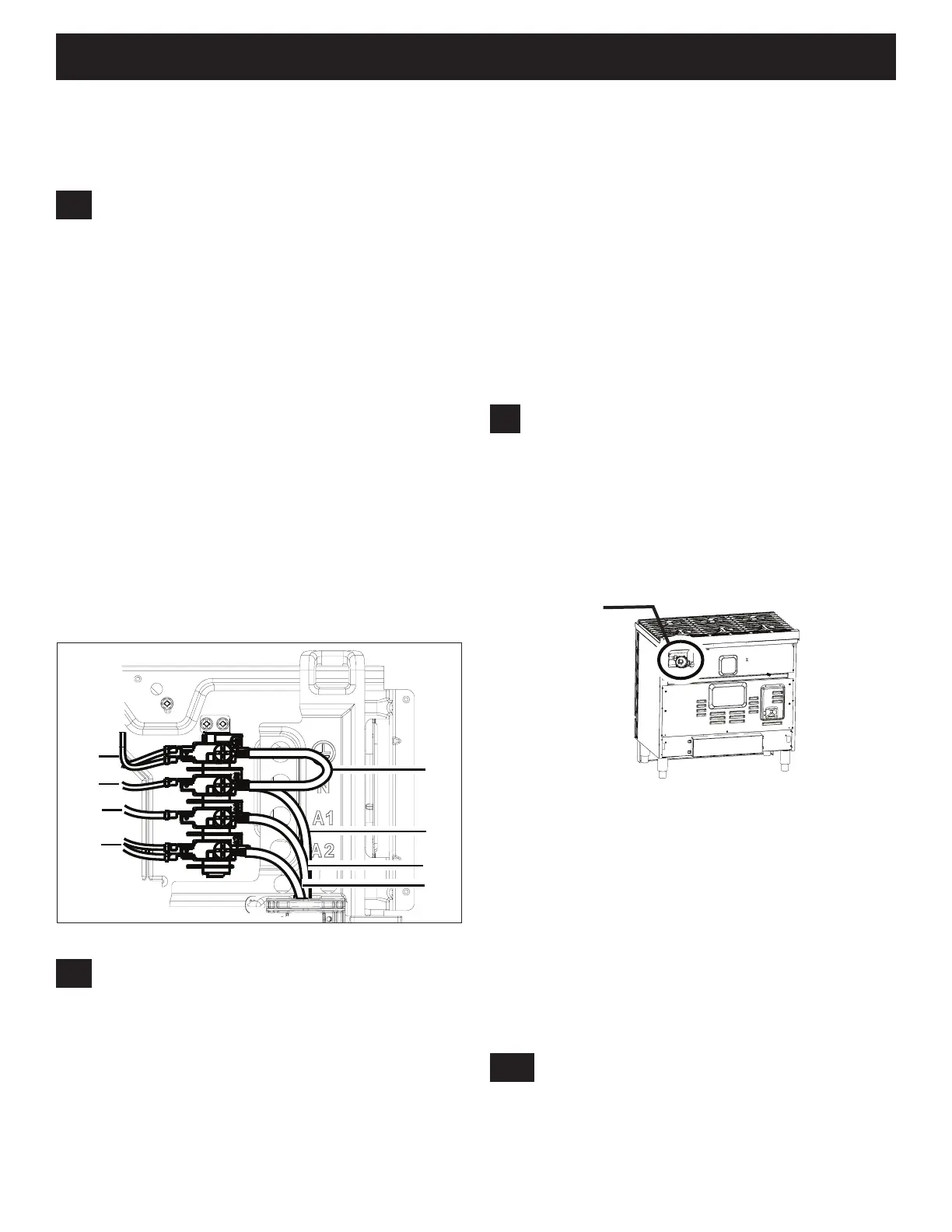
3 WIRE
GREEN
WHITE
BLACK
RED
GREEN
WHITE
BLACK
RED
Figure 9: 3 Wire Power Supply Cord Connection
3.4
3 Wire Power Cord Installation (for
non-terminated ends)
1. Remove two screws at the top of the Terminal
Block cover using Phillips head screwdriver.
2. Follow the manufacturer’s installation
instructions supplied with the strain relief (Strain
relief not supplied with unit) and install it.
3. Find the ground strap and metal adapter (4X)
supplied in the kit. We will be using only 3
adapters for this type of installation.
3.3
3 Wire Power Cord Installation
1. Remove two screws at the top of the Terminal
Block cover using Phillips head screwdriver.
2. Follow the manufacturer’s installation
instructions supplied with the strain relief (Strain
relief not supplied with unit) and install it.
3. Find the ground strap provided in the kit.
Remove the green color ground screw, slip the
one end of the strap on it and then screw the
ground screw back into its intended location.
4. Combine the neutral (white) wire from the
power cord with the other end of the ground
strap and screw it together by removing the
screw, slipping them in the screw and screwing it
to the intended location.
5. Make the remaining 2 connections as per the
color coding shown in figure 9. Make sure the
wire colors are matching after all connections
are made.
4
Fuel Supply Requirements
This unit is designed to operate on 4"(10.16 cm)
water column (1.0 kPa) natural gas manifold
pressure.
A convertible pressure regulator is supplied with
the unit. It must be connected in series with the
gas supply line using instructions from section 4.1
The intended location for the regulator is shown in
Figure 10.
Figure 10: Regulator location
For proper operation, the maximum inlet pressure
to the regulator should be no more than 14" (35.56
cm) of water column pressure (3.5 kPa).
The inlet pressure to the regulator must be at least
1"(0.25 kPa) greater than the regulator manifold
pressure setting. The regulator is set for 4" (10.16
cm) water column (1.0 kPa) Natural gas manifold
pressure; the inlet pressure must be at least 5"
(12.60 cm) water column (1.25 kPa) Natural gas.
For operation at 2000 ft. above sea level,
appliance rating is reduced by 4 percent for each
additional 1000 ft.
Regulator location
4.1
Regulator installation
There are 2 dierent types of installation for
regulators. Please check the regulator assembly
kit provided with the unit to identify which of the
following installations applies to your range.
4. Unscrew the green color ground screw, slip the
one end of the strap on it and screw it to the
intended location.
5. Connect the other end of the strap together with
the metal adapter at intended location of neutral
(white) wire.
6. Attach the adapters to the remaining 2 locations
(red and black).
7. Make the connection of the power cord wires
with metal adapter as mentioned in the section
3.2 point 4.
8. Make sure the wire colors are matching after
connections are made as per figure 9.
5. Follow the color coding shown in the figure 7 to
make all 4 connections.
6. Reinstall the terminal block cover.
Important: The ground strap should be installed
and must not be removed for electrical safety
when using 3 wire power cord.
Bekijk gratis de handleiding van Frigidaire GCFD3661SS, stel vragen en lees de antwoorden op veelvoorkomende problemen, of gebruik onze assistent om sneller informatie in de handleiding te vinden of uitleg te krijgen over specifieke functies.
Productinformatie
| Merk | Frigidaire |
| Model | GCFD3661SS |
| Categorie | Fornuis |
| Taal | Nederlands |
| Grootte | 10322 MB |


